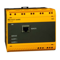
Do you have a question about the Bender ISOMETER isoPV425 and is the answer not in the manual?
Guidance on interpreting manual symbols and general usage instructions.
Contact information and services offered by Bender for technical assistance and product support.
Information on available training programs and workshops for Bender equipment.
Details regarding the sale and delivery terms, including software clauses.
Instructions for checking package integrity, handling, and proper storage conditions.
Exclusions for warranty and liability claims based on device misuse or unauthorized modifications.
Guidelines for the proper disposal of the device in accordance with environmental regulations.
Overview of general safety precautions and reference to separate safety documentation.
Guidelines for skilled personnel performing work on electrical installations, emphasizing risk of electric shock.
Defines the specific application of the ISOMETER® isoPV425 for monitoring unearthed AC/DC circuits.
Key features and capabilities of the ISOMETER® isoPV425, including monitoring and signaling functions.
Detailed explanation of how the ISOMETER® measures insulation resistance and system parameters.
Describes the parameters 'R1' and 'R2' for monitoring insulation resistance and alarm signaling.
Explains the monitoring of nominal system voltage (Un) for undervoltage and overvoltage conditions.
Details the device's self-test function, error detection, and corresponding error codes.
Defines operating time, response delay, and delay on release for measurement and alarm functions.
Overview of supported communication protocols like BMS, Modbus RTU, and IsoData.
Instructions for mounting the device using DIN rail or screw fixing methods.
Schematic diagram illustrating the correct connections for the ISOMETER® and AGH420.
Steps for initial setup, calibration, self-test, and functional checks after installation.
Explanation of the device's front panel display elements and their corresponding functions.
Overview of the device's menu system, navigation, and parameter selection.
Configuration of response values for alarm thresholds, including pre-alarm and alarm levels.
Configuration for fault memory, alarm relays, and interface settings.
Configuration of timing parameters such as start-up delay and response delay.
Configuration of device settings like password protection and factory reset.
How measured values are displayed and managed in the history memory.
Procedure for reading data from the ISOMETER®'s Modbus registers.
Instructions for writing parameters to the ISOMETER® via Modbus.
Explanation of Modbus exception codes used for error reporting.
Defines the data types and formats for ISOMETER® device information, including values and alarms.
Provides descriptions and codes for various measured values and alarm messages.
Presents technical specifications in a detailed tabular format.
Lists compliance with relevant industry standards and certifications.
Provides product codes and part numbers for ordering the device and accessories.
| Type | ISOMETER |
|---|---|
| Model | isoPV425 |
| Measuring current | < 1 mA |
| SIL | SIL 2 |
| Frequency range | DC |
| Protection class | IP20 |
| Insulation resistance | up to 10 MΩ |
| Operating temperature | -25…+70 °C |
| Storage temperature | -40 °C ... +70 °C |
| Relative humidity | ≤ 95 %, non-condensing |
| Display | LEDs |


