Operation of the device
34
isoPV425_D00028_09_M_XXEN/05.2018
5.3 Menu "AL"
5.3.1 Response value setting
The two parameters that monitor the insulation resistance, "R1" and "R2", can
be found in the response value menu "AL". The value R1 can only be set higher
than the value R2. If the insulation resistance R
F
reaches or falls below the ac-
tivated values R1 or R2, then this leads to an alarm message. If R
F
exceeds the
values R1 or R2 plus the hysteresis value (see table below), the alarm will be
cleared.
Also in the response value menu "AL" the parameters ("U <" and "U >") for
monitoring the nominal system voltage U
n
can be activated or deactivated.
The maximum undervoltage value is limited by the overvoltage value.
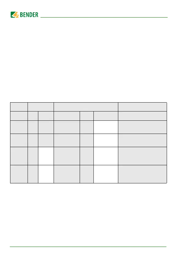
FAC = Factory setting; Cs = User settings
Display Activation Setting value Description
FAC Cs Value range
FAC Cs
R1 < R2 … 500 10 kΩ
Pre-alarm value R
an1
Hys. = 25 %/min. 1 kΩ
R2 < 1 … R1 5 kΩ
Alarm value R
an2
Hys. = 25 %/min. 1 kΩ
U < off 30 … U> 30 V
Alarm value
undervoltage
Hys . = 5 %/min. 5 V
U > off
U< … 1.15 k
1000 V
Alarm value
overvoltage
Hys. = 5 %/min. 5 V