Function
20
isoPV425_D00028_09_M_XXEN/05.2018
3.2.4 Malfunction
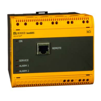
In addition to the self test described above, several functions in the insulation
monitoring device are continuously checked during operation. If a fault is de-
tected, the device error ("Err") will be signalled, the error code "E.xx" appears
on the display as an identifier for the error type xx and the LEDs "ON"/"AL1"/
"AL2" will flash. If the error occurs again after restarting the device or after a
reset to factory settings, then contact Bender Service.
3.2.5 Signalling assignment of the alarm relays K1/K2
The messages "device error", "insulation fault", "insulation impedance fault",
"undervoltage/overvoltage fault", "device test" or "device start with alarm"
can be assigned to the alarm relays via the "out" menu. An insulation fault is
indicated by the messages "+R1", "-R1", "+R2" and "-R2". Messages "+R1" and
"+R2" indicate an insulation fault assigned to conductor L1/+, and the mes-
sages "-R1" and "-R2" indicate an insulation fault assigned to conductor L2/-. If
an assignment is not possible, for example in the event of a symmetrical insu-
lation fault, the messages corresponding to + and - are shown together.
The message "test" indicates a self test.
The message "S.AL" indicates a so-called "device start with alarm". After con-
necting to the supply voltage U
s
and setting the parameter value to
"S.AL = on", the ISOMETER® starts with the insulation measurement value
R
F
= 0 Ω and sets all activated alarms.
The alarms will be cleared only when the measured values are up-to-date and
no thresholds are exceeded. In the factory setting "S.AL = off", the ISOMETER®
starts without an alarm.
It is recommended that the value set for the "S.AL" parameter value is identi-
cal for both relays.

 Loading...


