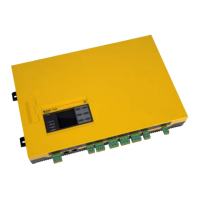
Do you have a question about the Bender ISOMETER isoRW425 and is the answer not in the manual?
Refers to separate safety instructions document and general safety precautions.
Specifies that only skilled persons can perform installation, commissioning, and operation.
Defines the function of the ISOMETER® for monitoring insulation resistance/impedance in unearthed IT systems.
Lists the key features and capabilities of the ISOMETER® device.
Explains how the ISOMETER® measures insulation resistance, impedance, and system voltage.
Details how the device monitors insulation resistance and sets alarm thresholds.
Explains monitoring insulation impedance, including formula calculation.
Describes the monitoring of mains voltage for undervoltage and overvoltage conditions.
Explains the integrated self-test function and how error codes are displayed.
Details how malfunctions are signaled and what to do if errors persist.
Explains how to assign functions to alarm relays and LED indications.
Provides instructions for mounting the device using DIN rail or screw fixing.
Details how to connect the device to the supply voltage and protective device.
Outlines the steps for checking connections, connecting supply voltage, and performing self-tests.
Presents technical specifications in a tabular format, including insulation coordination.
| Measurement Principle | Insulation monitoring device for unearthed AC and DC systems |
|---|---|
| Resolution | 1 kΩ |
| Test Voltage | > DC 30 V |
| Display | Multilingual plain text display |
| Operating Temperature | -10°C to +55°C |
| Power Supply | AC/DC 24 V to 265 V |
| Weight | Approx. 270 g |
| Automatic adaptation to the system leakage capacitance | Yes |
| Two separately adjustable response values | Yes |
| N/C or N/O operation selectable | Yes |
| Automatic device self test | Yes |
| Connection monitoring (L1-PE, N-PE) | Yes |
| Modbus RTU interface | Yes |
| History memory with real-time clock | Yes |
| Parameterisation via display, PC or Modbus | Yes |
| Measurement range | 0-10 MΩ |


