Device operation
32
isoRW425_D00052_03_M_XXEN / 02.2017
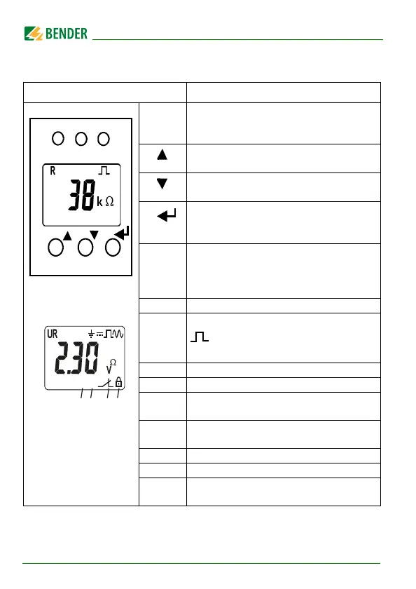
5.1 Display elements in use
Device front/display Function
ON
AL1
AL2
green - on
yellow - alarm
yellow - alarm
t
Up button
Test button ( press > 1.5 s)
R
Down button
Reset button (press > 1.5 s)
MENU
ENTER
MENU button (press > 1.5 s)
1U : Mains voltage
R : InsuIation resistance
Z : Insulation impedance
C : Leakage capacitance
2 Monitored conductor
3 = : Voltage type DC
~ : Voltage type AC
4 Measured values and units
5 Password protection is activated
6 In the menu mode, the operating mode of
the respective alarm relay is displayed
7 Communication interface
With measured value: isoData operation
8 The fault memory is activated
9 Status indicators
10 Identification for response values and
response value violation
+
test onoff MAdr
L1L2
C
<
>
s
kM %
Fµ
{
{
{
{
1
2
3
5
67
8
{
9
Z
Hz
{
10
: Error-free measuring value update
Assignment according to
table on Page 35