Device operation
34
isoRW425_D00052_03_M_XXEN / 02.2017
5.3 Menu "AL"
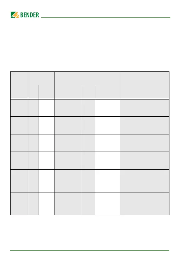
5.3.1 Response value setting
Only after activating Z mode in the "SEt" menu, the response values Z1 as well
as Z2 appear on the display and are activated. Simultaneously, the response
values R1 and R2 are set to position off, but can then be set to on again.
FAC = Factory setting; Cs = User settings
Display Activation Setting value Description
FAC Cs Range
FAC Cs
R1 < ON R2 … 990 40 kΩ
Pre-alarm value R
an1
Hys. = 25% / min. 1k
R2 < ON 1 … R1 10 kΩ
Alarm value R
an2
Hys. = 25% / min. 1k
Z1 < OFF Z2 … 500 60 kΩ
Pre-alarm value Z
an1
Hys. = 25% / min. 1k
Z2 < OFF 10 … Z1 50 kΩ
Alarm value Z
an2
Hys. = 25% / min. 1k
U < OFF 10 … "U>" 30 V
Alarm value
undervoltage
Hys. = 5% / min. 5V
U > OFF
"U<" … 500
500 V
Alarm value
overvoltage
Hys. = 5% / min. 5V