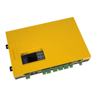
Do you have a question about the Bender ISOMETER iso1685D Series and is the answer not in the manual?
Guidance on effective use of the manual for understanding and reference.
Information on available technical support services for commissioning and troubleshooting.
Details on dates and locations for training courses and workshops.
Regulations and directives for proper disposal of electrical and electronic equipment.
General safety guidelines and warnings for using Bender products.
Specific safety warnings and risks related to the ISOMETER® device itself.
Defines the proper application and scope of use for the ISOMETER® device.
Overview of the key features and capabilities of the ISOMETER® iso1685Dxx.
Detailed description of the ISOMETER® iso1685Dxx and its application in IT systems.
Explanation of how insulation monitoring and fault location functions operate.
Details on the device's self-testing procedures upon power-up and periodically.
Physical dimensions and mounting specifications of the ISOMETER® device.
Description of all terminal connections and their functions on the device.
Identification and function of the device's display, LEDs, and buttons.
Instructions for physically mounting and installing the ISOMETER® device.
General guidelines and requirements for connecting the ISOMETER® to the system.
Detailed step-by-step procedure for wiring the ISOMETER® device.
Wiring diagrams for AC systems and with insulation fault locators.
Visual guides for commissioning insulation fault monitoring and location.
Step-by-step guide for the initial setup and configuration of the device.
Procedure for restarting the commissioning wizard for already operated devices.
Instructions for putting an EDS insulation fault locator into operation with the ISOMETER®.
Description of the normal operating display and measured values.
How active and inactive faults are displayed, including LED indicators and messages.
Graphical representation of insulation resistance over time.
Accessing and managing stored alarm and device error messages.
Display indications related to the active insulation fault location function.
Structure and organization of the device's menu system.
How to navigate through menus and adjust settings using device buttons.
Configuration of alarm levels (Ran1, Ran2) and hysteresis for insulation faults.
Selection of system profiles to optimize insulation monitoring performance.
Configuration of device operation mode, coupling monitoring, and digital inputs.
Configuration of alarm relays (K1, K2, K3) and buzzer functions.
Settings related to the EDS insulation fault location feature, including modes and current.
Options for viewing measured data, performing tests, and resetting alarms.
Configuration of device language, date, time, and summer time settings.
Settings for BMS bus communication, display brightness, and password protection.
Default configuration values for measurement, alarms, profile, and other parameters.
Details on the RS-485 physical interface and BMS protocol.
Recommended and incorrect wiring topologies for RS-485 networks.
Role of the BMS master, protocol details, and address assignment.
List of alarm/operating messages and error codes with recommended actions.
Introduction to the function and essential settings for insulation fault location.
How the display indicates the function and methods to start/stop it.
Graphs showing response time vs. resistance for different system profiles and leakage capacitances.
Graph showing the minimum limiting condition for determining capacitance value.
Comprehensive table of technical specifications and parameters for the ISOMETER®.
List of standards and certifications the device complies with.
Information on product types, response values, nominal voltages, and article numbers.
| Brand | Bender |
|---|---|
| Model | ISOMETER iso1685D Series |
| Category | Measuring Instruments |
| Language | English |


 Loading...