SettingsSettings
iso1685DP_D00272_03_M_XXEN/08.2017
30
9.1 (1.4) Device
Set the ISOMETER® insulation resistance measurement function to active or inactive:
9.1 (1.5) Coupling monitoring
The coupling is monitored at 24-hour intervals. This monitoring function can be activated
or deactivated.
9.1 (1.6) Inputs
The ISOMETER® provides 2 digital inputs (I1, I2) that are freely configurable.
9.1 (1.6.1) Digital 1
The following parameters can be set for the digital input:
9.1 (1.6.1.1) Mode
The operating mode for the digital input can be set to the following values:
•Active
The device is active.
•Inactive
The device DOES NOT measure the insulation resistance and
is disconnected from the system to be monitored (system
disconnection). The IT system is NOT being monitored!
The message Device inactive appears on the display. The
ALARM1 and ALARM2 LEDs are lit.
•on
Coupling monitoring is activated.
•off
Coupling monitoring is deactivated.
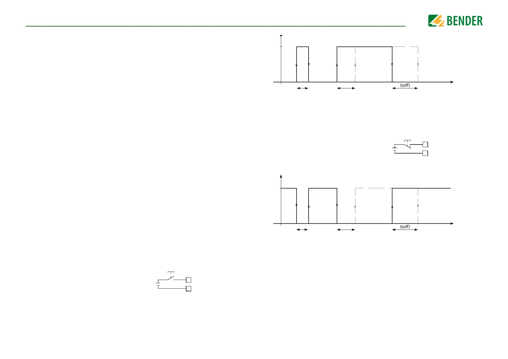
•Active high
An event is carried out on the rising edge of the
digital input (low to high).
Response time t(on)/t(off) after a switch-on sig-
nal.
9.1 (1.6.1.2) t(on)
The response time t(on) after a switch-on signal can be set between 100 milliseconds and
300 seconds.
9.1 (1.6.1.3) t(off)
The response time t(off) after a switch-off signal can be set between 100 milliseconds and
300 seconds.
•Active low
An event is carried out on the falling edge of the
digital input (high to low).
Response time t(on)/t(off) after a switch-off sig-
nal.
t
0
1
t(on)
Reaction
Impulse on
Reaction
t
0
1
t(on)
Reaction Reaction
< t(on)