Device communication via the BMS busDevice communication via the BMS bus
iso1685DP_D00272_03_M_XXEN/08.2017
38
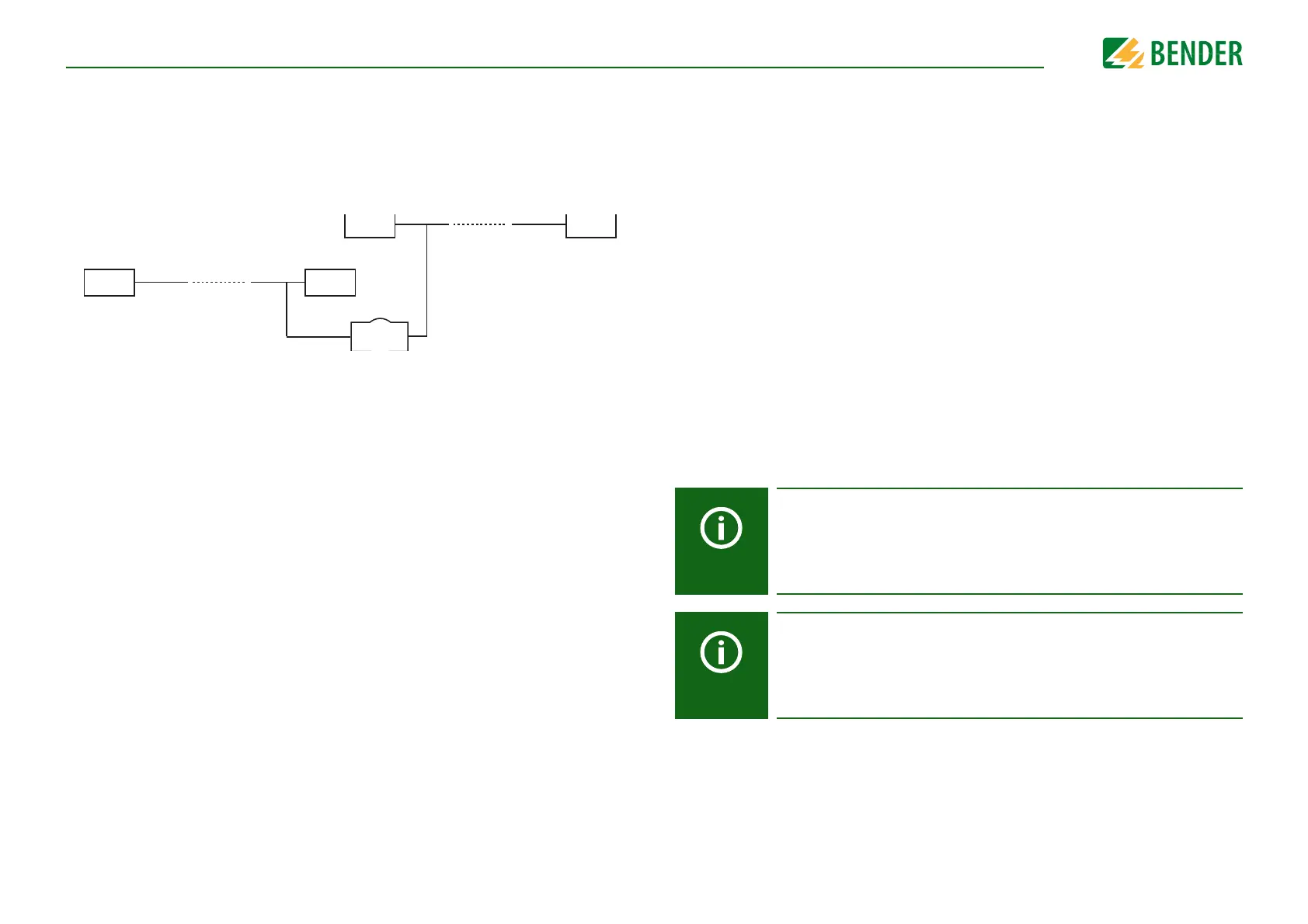
Wiring
The following type of wiring is recommended for the RS-485 network:
Shielded cable, core diameter ³ 0.8 mm
(e.g. J-Y(St)Y 2x0.8), shield connected to earth (PE) on one end.
Connection to terminals A and B.
The number of bus nodes is restricted to 32 devices. If more devices are to be connected,
Bender recommends the use of a DI1 repeater.
10.3 BMS protocol
This protocol is an essential part of the Bender measuring device interface (BMS bus pro-
tocol). Data transmission generally makes use of ASCII characters.
Interface data are:
• Baud rate: 9600 baud
• Transmission: 1 start bit, 7 data bits, 1 parity bit, 1 stop bit (1, 7, E, 1)
• Parity: even
• Checksum: sum of all transmitted bytes = 0 (without CR and LF)
The BMS bus protocol works according to the master-slave principle. Only one master
may exist in each network. All bus devices are identified by a unique BMS address. The
master cyclically scans all other slaves on the bus, listens to their signals and then carries
out the corresponding commands.
A device receives the MASTER function by assigning Bus address 1 to it.
10.4 BMS master
A master can query all measured values, alarm and operating messages from a slave. If
bus address 1 is assigned to a device, this device automatically represents the master, i.e.
all addresses between 1 and 150 are cyclically scanned via the BMS bus for alarm and op-
erating messages. If the master detects incorrect answers from a slave, the fault message
"Fault RS-485" will be output via the BMS bus.
Fault causes may be:
• Addresses are assigned twice
• A second master exists on the BMS bus
• Interference signals occur on the bus lines
• A defective device is connected to the bus
• Terminating resistors are not activated or connected
10.5 Commissioning of an RS-485 network with BMS protocol
• Interconnect terminals A and B of all bus devices in one line
• Switch the terminating resistors on at the start and the end of the RS-485 network. If
a device at the end of the bus is not terminated, connect a 120 resistor to termi-
nals A and B
• Switch the supply voltage on
• Assign the master function and address 1 to a bus-capable device
• Assign addresses (2…90) to all other bus devices in consecutive order
10.6 Setting BMS address
Set the BMS address ((1)2…90) in the device menu via the path:
Device settings/Interface/BMS/BMS Address.
The ISOMETER® cannot switch on a potential termination at the BMS bus.
Even though this is not expected to cause communication problems, the
ISOMETER® should be operated as BMS slave if possible (BMS address > 1).
If no other device with master capabilities is available on the bus, the
ISOMETER® can be set to master (BMS address 1).
Before the ISOMETER® takes over the backup master function after being
switched on, it waits to see if another master connects itself to the system.
Waiting period: BMS address minus 1 = waiting period in minutes.
Example: The iso1685DP has BMS address 3. It waits 3 minus 1 minutes
(= 2 minutes) for a master to connect.