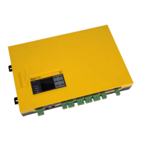
Do you have a question about the Bender ISOMETER isoEV425 and is the answer not in the manual?
Information on contacting Bender for first-level support, repair services, and field service operations.
Specifies that only skilled persons can perform installation, commission, and operation work.
Explains how the ISOMETER® measures insulation resistance, voltage, and handles faults and alarms.
Illustrates the electrical connections and terminal assignments for the ISOMETER® and AGH420.
Details the steps for device calibration, self-testing, and initial functional checks after installation.
Instructions for requesting and reading data from the ISOMETER® using Modbus function codes.
Procedures for modifying device parameters by writing to registers via the Modbus protocol.
Defines the data formats, including device name and measured values, for Modbus communication.
Maps numerical values and codes to specific measured values and alarm messages for Modbus channels.
| Brand | Bender |
|---|---|
| Model | ISOMETER isoEV425 |
| Category | Measuring Instruments |
| Language | English |


 Loading...