Safety instructions
13
isoEV425_D00126_09_M_XXEN/03.2019
2.3 Intended use
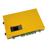
The ISOMETER® of the isoEV425 or isoEV425HC series monitors the insulation
resistance R
F
of unearthed AC/DC main circuits (IT systems) with nominal sys-
tem voltages of 3(N)AC, AC/DC 0 … 690 V or DC 0 …1,000 V. The main appli-
cation areas are unearthed DC charging stations (mode 4 acc. to IEC 61851-23)
for electric vehicles (IT systems) with nominal system voltages of
DC 0 … 1,000 V. DC components existing in 3(N)AC, AC/DC systems do not in-
fluence the operating characteristics, when a minimum load current of
DC 10 mA flows. A separate supply voltage U
s
allows deenergised systems to
be monitored as well. The maximum permissible system leakage capacitance
C
e
is 5 µF (for isoEV425) and 20 µF (for isoEV425HC). The ISOMETER® is always
used in conjunction with the coupling device AGH420.
To ensure that the ISOMETER® functions correctly, an internal
resistance of ≤ 1 kΩ must exist between L1/+ and L2/- via the
source (e.g. the transformer) or the load.
 Loading...


