43
isoEV425_D00126_09_M_XXEN/03.2019
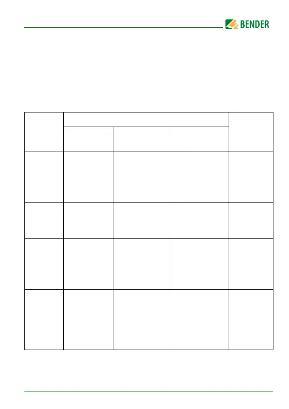
8. Modbus register assignment of the ISOMETER®
Depending on the device condition, the information in the registers is: the
measured value without alarm, the measured value with alarm 1, the
measured value with alarm 2 or only the device fault.
Register
Measured value
Device fault
Without
alarm
Alarm 1 Alarm 2
1000
to
1003
R
F
Insulation
fault (71)
[no alarm]
R
F
Insulation
fault (1)
[pre-warning]
R
F
Insulation
fault (1)
[alarm]
---
Connection
earth (102)
[Device
fault]
1004
to
1007
--- --- ---
---
1008
to
1011
U
n
Voltage (76)
[no alarm]
U
n
Undervoltage
(77)
[alarm]
U
n
Overvoltage
(78)
[alarm]
---
Connection
system (101)
[device
fault]
1012
to
1015
C
e
System leak-
age
capacitance
(82)
[no alarm]
--- --- ---