Modbus register assignment of the ISOMETER®
53
isoEV425_D00126_09_M_XXEN/03.2019
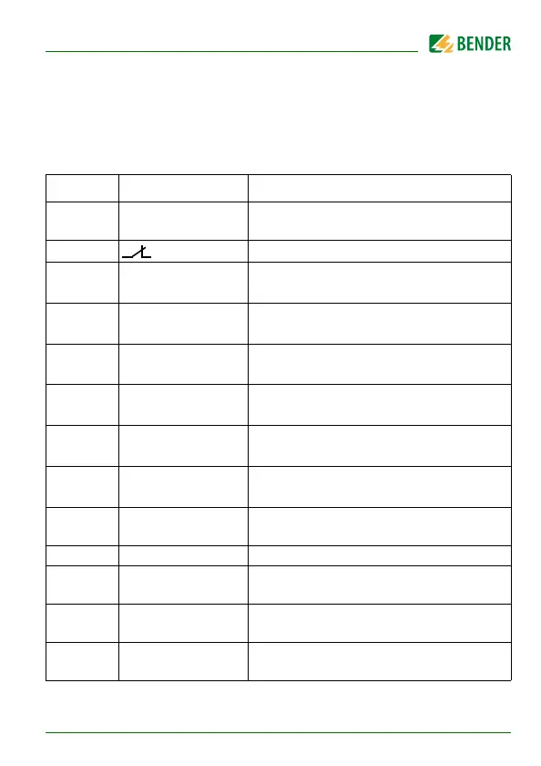
8.1.3 Alarm assignment of the relays
Several alarms can be assigned to each relay. For the assignment of each relay,
a 16-bit register is used with the bits described below. The following table ap-
plies to relay 1 and relay 2, in which "x" stands for the relay number. A set bit
activates the specified function.
Bit Display indication Description
0Reserved
When reading, always 0
When writing, any value
1 x Err Device error E.xx
2
rx
+R1 <
Pre-alarm R1
Fault R
F
at L1/+
3
rx
-R1 <
Pre-alarm R1
Fault R
F
at L2/-
4
rx
+R2 <
Alarm R2
Fault R
F
at L1/+
5
rx
-R2 <
Alarm R2
Fault R
F
at L2/-
6
rx
U < V
Alarm message U
n
Undervoltage
7
rx
U > V
Alarm message U
n
Overvoltage
8
rx
test
Manually started self test
9 S.AL Device start with alarm
10 Reserved
When reading, always 0
When writing, any value
11 Reserved
When reading, always 0
When writing, any value
12 Reserved
When reading, always 0
When writing, any value