Operation of the device
33
isoEV425_D00126_09_M_XXEN/03.2019
5.4 Menu "out"
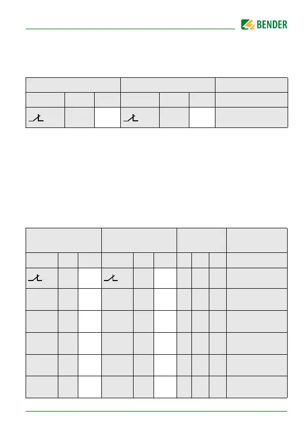
5.4.1 Configuration of the relay operating mode
FAC = Factory setting; Cs = User settings
5.4.2 Relay alarm assignment "r1" and "r2" and LED assignment
In the alarm assignment, each alarm is assigned to the respective relay with
the setting "on". The LED indication is directly assigned to the alarms and is
not related to the relays.
In the event of an unsymmetrical insulation fault, only the alarm correspond-
ing to the assigned conductor (L1/+ or L2/-) will be displayed. Otherwise, the
messages for L1/+ and L2/- are shown together.
Relay K1 Relay K2 Description
Display FAC Cs Display FAC Cs
n.c. n.c.
Operating mode of
the relay n.c./n.o.
K1 "r1" K2 "r2" LEDs
Alarm
description
Display
FAC Cs
Display
FAC Cs
ON AL1 AL2
off on
Device error E.xx
r1
+R1 <
on
r2
+R1 <
off
Pre-alarm R1
Fault R
F
at L1/+
r1
-R1 <
on
r2
-R1 <
off
Pre-alarm R1
Fault R
F
at L2/-
r1
+R2 <
off
r2
+R2 <
on
Alarm R2
Fault R
F
at L1/+
r1
-R2 <
off
r2
-R2 <
on
Alarm R2
Fault R
F
at L2/-
r1
U < V
off
r2
U < V
on
Alarm U
n
Undervoltage