Do you have a question about the Bender ISOMETER iso685-D-P and is the answer not in the manual?
Provides guidance on how to understand and use the manual effectively.
Details contact information for commissioning and troubleshooting assistance.
Information on on-site services, including commissioning and analysis.
Information on available training dates and workshops for test equipment.
Outlines Bender's sale and delivery conditions for products and software.
Instructions for inspecting, transporting, and storing the device safely.
Details warranty exclusions and liability claims related to device usage.
Information on adhering to regulations for the disposal of electrical equipment.
General safety guidelines applicable to Bender products.
Specifies that only qualified personnel may perform work on electrical installations.
Provides safety warnings and precautions specific to the ISOMETER® device.
Lists key features and capabilities of the ISOMETER® and EDS44... devices.
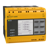
Provides a general description of the ISOMETER® and its variants.
Explains how the insulation monitoring device operates and triggers alarms.
Describes the function of selective insulation fault location using the EDS.
Details the communication interfaces available on the device.
Explains the automatic and manual self-test functions of the ISOMETER®.
Lists compatible EDS devices and their combination possibilities.
Provides the physical dimensions of the ISOMETER® device.
Describes the different ISOMETER® device variants and their features.
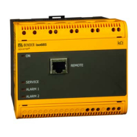
Illustrates the device's terminal connections and panel layout.
Explains the function of display elements and device control buttons.
General instructions for mounting the device, emphasizing qualified personnel.
Step-by-step guide for mounting the ISOMETER® using screws.
Instructions for mounting the ISOMETER® securely onto a DIN rail.
Specifies minimum clearance requirements for connecting adjacent devices.
Wiring diagram and instructions for connecting to a 3(N)AC system.
Wiring diagram and instructions for connecting to a single-phase AC system.
Wiring diagram and instructions for connecting to a DC system.
Details the connections for the multifunctional I/O interface (X1).
Instructions for connecting the device to the supply voltage.
Instructions for establishing an Ethernet connection for communication.
Wiring details for the relay 1 interface (terminals 11, 12, 14).
Wiring details for the relay 2 interface (terminals 21, 22, 24).
Information on connecting to the BB bus for device communication.
Guides on how to connect EDS devices to the ISOMETER®.
Illustrates a connection example between ISOMETER® and EDS devices.
Wiring example for connecting ISOMETER® and EDS to a 3(N)AC system.
Wiring example for connecting ISOMETER® and EDS to an AC system.
Wiring example for connecting ISOMETER® and EDS to a DC system.
Shows an example application of monitoring a control system with ISOMETER® and EDS.
Step-by-step guide for the initial commissioning of the ISOMETER®.
Details the steps for initial commissioning, including language and system type.
Describes how to restart the commissioning wizard for existing devices.
Procedure for putting an EDS device into operation after ISOMETER® commissioning.
Explains the standard operational display showing OK status and measured resistance.
Describes how active faults are indicated on the display and via LEDs.
Explains how inactive faults are indicated, showing past fault conditions.
Procedure for acknowledging fault messages and clearing the fault memory.
Details the isoGraph function for chronological representation of insulation resistance.
Explains the history memory for storing alarm messages and device errors.
Describes how insulation fault location is indicated on the ISOMETER® display.
Explains the initial measurement process and data recording.
Provides a hierarchical overview of the device's menu structure.
Guides on how to navigate and operate the device menu using its buttons.
Covers the configuration of device settings within the menu system.
Configuration of alarm limit values for alarm 1 and alarm 2.
Adaptation of the ISOMETER® application area to system profiles.
Setting the system type to optimize insulation monitoring accuracy.
Configuration and activation/deactivation of the ISOnet function.
Configuration parameters for the three digital inputs.
Configuration parameters for the six available outputs (relays, buzzer, digital).
Settings related to the EDS for insulation fault location.
Viewing stored measured values like isoGraph, insulation, and system data.
Functions for starting manual tests, resetting alarms, and initial measurements.
Accessing and resetting the fault history memory.
Basic configuration settings for the ISOMETER®.
Selection of the display language for the ISOMETER® menu.
Setting the display format for time and date, including summer time.
Setting parameters for connecting other devices via interfaces.
Viewing current device settings such as software, IP address, and BS bus.
Displays default factory settings for parameters and interfaces.
Using the Ethernet interface for Modbus, web server, and BCOM communication.
Protocol for communication between Bender devices via Ethernet.
International protocol for data transfer between devices using Modbus TCP.
Using the integrated web server to display data and parameterize devices.
Interface for extending Bender devices with sensor devices using RS-485.
Explains the selective insulation fault location function with EDS.
Details necessary settings for connecting and commissioning ISOMETER® and EDS.
Describes how active insulation fault location is indicated on the ISOMETER® display.
Methods for starting and stopping the insulation fault location process.
Notes on monitoring coupled IT systems with multiple ISOMETER® devices.
Using digital inputs to isolate and deactivate ISOMETER® in coupled systems.
Ensuring only one active ISOMETER® in an interconnection via Ethernet.
Response time as a function of response value and system leakage capacitance.
Response time for control circuits based on response value and capacitance.
Response time characteristics for generator monitoring applications.
Response time profiles for systems with high system leakage capacitance.
Response time profiles for inverters operating above 10 Hz.
Response time profiles for inverters operating below 10 Hz.
Graph showing operating uncertainty as a function of response value and capacitance.
Lists alarm messages for the ISOMETER®, their descriptions, measures, and references.
Lists alarm messages specific to the EDS, including causes and measures.
Presents technical specifications and coordination data in a tabular format.
Details specific data for devices with the 'W' option (enhanced resistance).
Lists the standards and certifications the ISOMETER® complies with.
Provides product types, supply voltages, and article numbers for ordering.
| Brand | Bender |
|---|---|
| Model | ISOMETER iso685-D-P |
| Category | Measuring Instruments |
| Language | English |


