Device communicationDevice communication
iso685-D-P_D00170_00_M_XXDE/06.2016
65
11.4 Web server
The ISOMETER® has an integrated web server which displays ISOMETER® data and data of
any associated devices (e.g. EDS) comfortably on every PC via a web browser.
The web server can be used to read out measured values and parameterise the
ISOMETER®s and the EDS.
The web server offers the following functions:
• Visualisation
• Indication of device information (e.g. device type, software version, etc.)
• Indication of current device settings.
• Indication of alarm messages.
• Indication of the Modbus information of the individual parameters.
• Indication of the interfaces in use.
• Overview of the current measured values.
• Detailed graphic representation of the insulation resistance (isoGraph).
• Fast and simple visualisation without any programming.
• Parameter setting
• Easy and fast parameter setting of the device and the connected EDS.
• Easy assignment and edition options of device and measuring channel texts.
• Maintenance
• Data storage of specific events for fast support by Bender Service.
A maximum of 5 TCP/IP connections can be used simultaneously.
Only one device may access the web server at the same time. If several de-
vices try to access the web server it may result in timeouts.
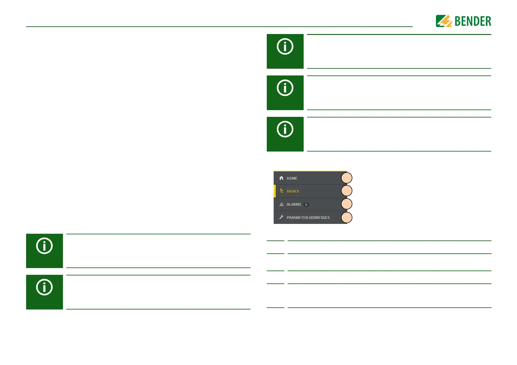
Web server device menu (first level)
Legend for web server device menu (first level)
The write access is deactivated by default in the device menu (= Deny). To
be able to set parameters via the web server the write access must first be
activated in the device menu (= Allow) (see “Write access” on page 61).
Use the web server preferably with the following web browsers:
Google Chrome, Mozilla Firefox or Internet Explorer.
If you deactivate EDS channels via the web server, no settings can be
made simultaneously on the EDS channels. The settings of deactivated
channels cannot be changed.
1 START Indication of general device information.
2DEVICE
Indication of an overview of alarm values and measured values.
Indication of the settings. Settings can be changed here.
3 ALARMS Indication of alarm messages.
4
PARAMETER
ADDRESSES
Activate and deactivate the indication of the Modbus information by
selecting or deselecting the selection box for the question "Display
additional Modbus information for each parameter?".