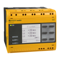
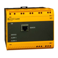
Do you have a question about the Bender ISOMETER iso685-D and is the answer not in the manual?
Specific safety precautions related to the ISOMETER® device and its operation.
Overview of the ISOMETER®'s features, product description, and functional capabilities.
Configuration of response values for Alarm 1 and Alarm 2, and fault memory settings.
Configuration of limit values for Alarm 1 and Alarm 2 for insulation resistance.
Adaptation of the ISOMETER®'s application area by selecting predefined profiles.
Activation and deactivation of DC alarm triggered by DC offset voltage in the system.
Details communication interfaces like Modbus TCP, BCOM, Ethernet, and web server.
Describes the terminal connections and front panel layout for system integration.
Specifies minimum distances to adjacent devices and general connection prerequisites.
Details the wiring procedure for connecting the ISOMETER® to a 3(N)AC system.
Details the wiring procedure for connecting the ISOMETER® to a DC system.
Explains how to connect the external power supply to the ISOMETER® via terminal X1.
Details the wiring procedure for connecting the ISOMETER® to a single-phase AC system.
Details the connection procedure for the Ethernet interface used for network communication.
Outlines the steps for initial setup and verification of the ISOMETER®'s connection and operation.
Guides through setting language, date, time, system type, and profile for optimal device performance.
Allows setting the prewarning response value for Alarm 1.
Allows setting the response value for the main alarm, Alarm 2.
Describes how inactive faults are displayed, indicating past faults without current fault condition.
Explains how active faults are indicated on the display, including color changes and alarm messages.
Enables communication for Modbus, web server, and BCOM via the Ethernet connection.
Integrated server for data visualization, parameter setting, and maintenance via web browser.
Ensures only one active ISOMETER® in interconnected systems and handling of coupled IT systems.
Describes isolating the ISOMETER® via a digital input using a coupling switch contact.
| Brand | Bender |
|---|---|
| Model | ISOMETER iso685-D |
| Category | Measuring Instruments |
| Language | English |


