Diagrams
iso685-D-B_D00177_05_M_XXEN/07.2017
56
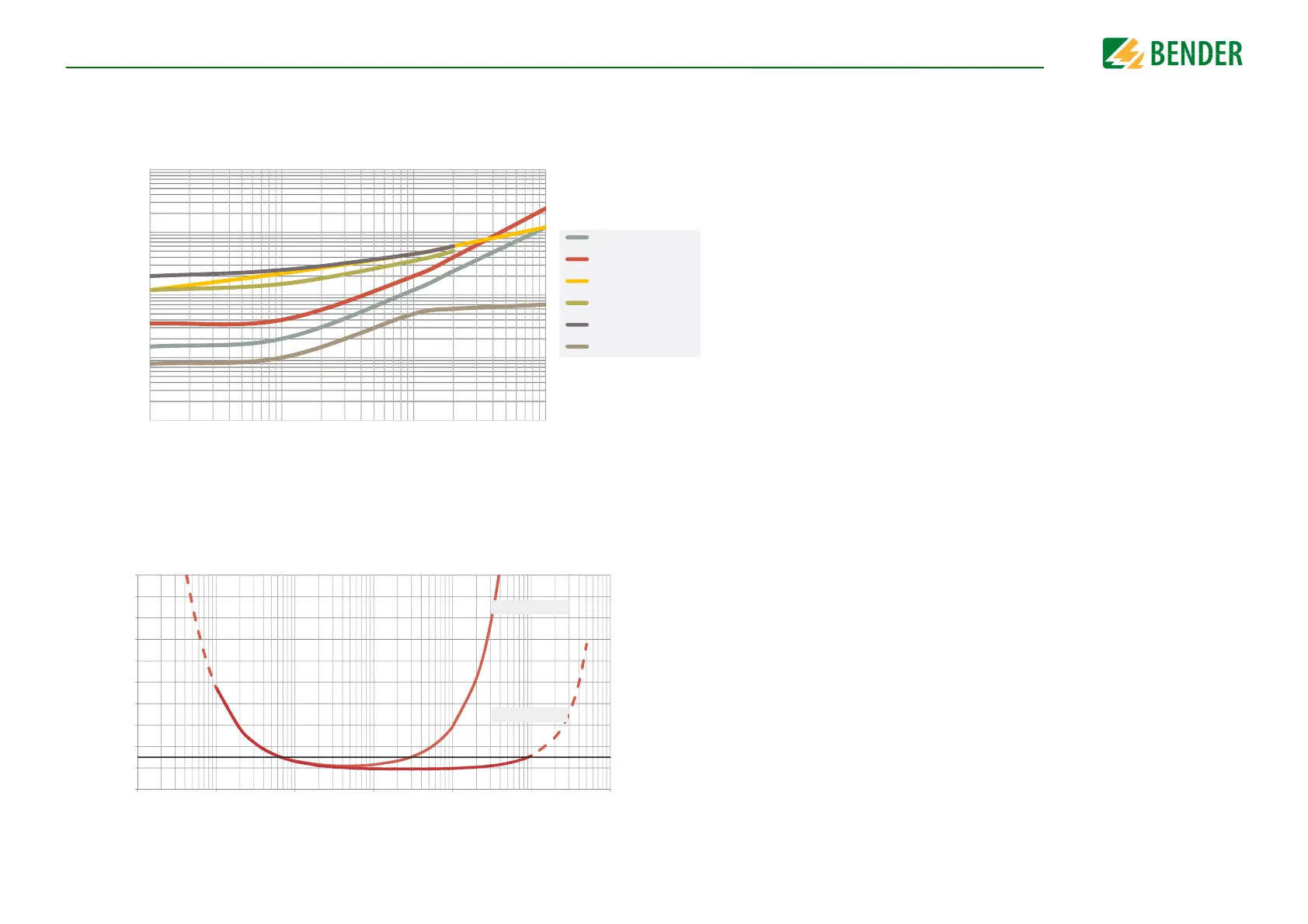
14.7 Response time DC alarm
14.8 Relative uncertainty
0,1
1
10
100
1000
0,1 1 10 100
system leakage capacitance [µF]
response time [sec]
Typical response time for DC alarm for R
F
=100KΩ depending on
system prole and system leakage capacitance
Power circuit
Control circuit
High capacitance
Inverter >10Hz
Inverter <10Hz
Generator
C
e
0.1 1 10 100 1000 10000 100000
Relative uncertainty as a function of the response value (R
an
) and system leakage
capacitance (C
e
) according to IEC 61557-8 (U
n
= AC 690 V, f
n
= 50 Hz)
0 %
90 %
80 %
70 %
60 %
50 %
40 %
30 %
20 %
10 %
100 %
Response value R
an
[kΩ]
Operating uncertainty [%]
C
e
≤ 1000 µF
C
e
≤ 1 µF