ConnectionConnection
iso685-D-B_D00177_05_M_XXEN/07.2017
20
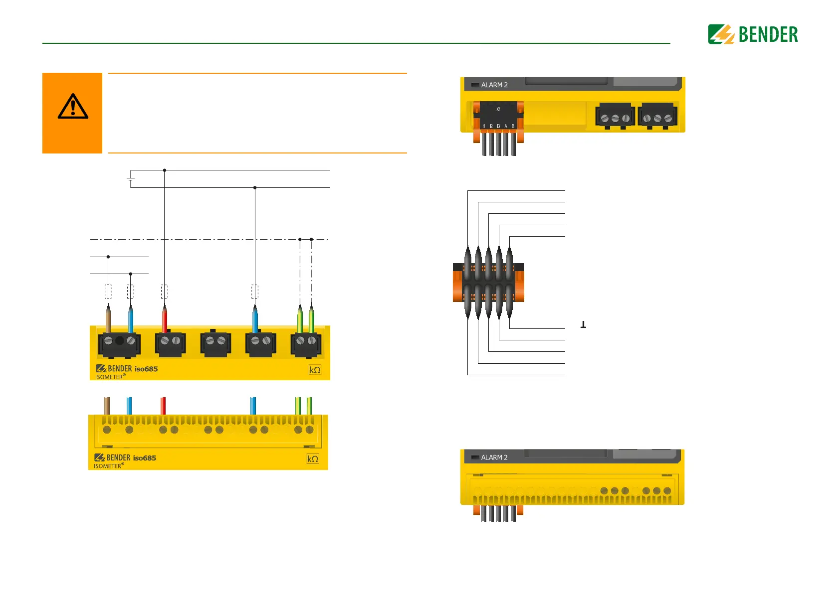
6.4 Connection to a DC system
Position the terminal cover and click it into place
For systems > 690 V and with overvoltage category III a fuse for
the connection to the system to be monitored must be provided.
Recommendation: 2 A fuses.
Risk of injury, fire and damage to property due to a short circuit!
According to DIN VDE 0100-430, devices used to protect against a short
circuit when terminals L1/+, L2 und L3/- are coupled to the IT system to be
monitored can be omitted if the wiring is carried out in such a manner as
to reduce the risk of a short circuit to a minimum. Ensure short-circuit-
proof and earth-fault-proof wiring.
6.5 Connection to the X1 interface
Position the terminal cover and click it into place
I1
I2
I3
A
B
M+
Q2
Q1
+
Electrical overload protection.
Auto shut-off in the event of a short
circuit and transients (resettable)
Input 1
Input 2
Input 3
RS-485 A
RS-485 B
Ground
Analogue output
Output 2
Output 1
+24 V