Device overview
iso685-D-B_D00177_05_M_XXEN/07.2017
14
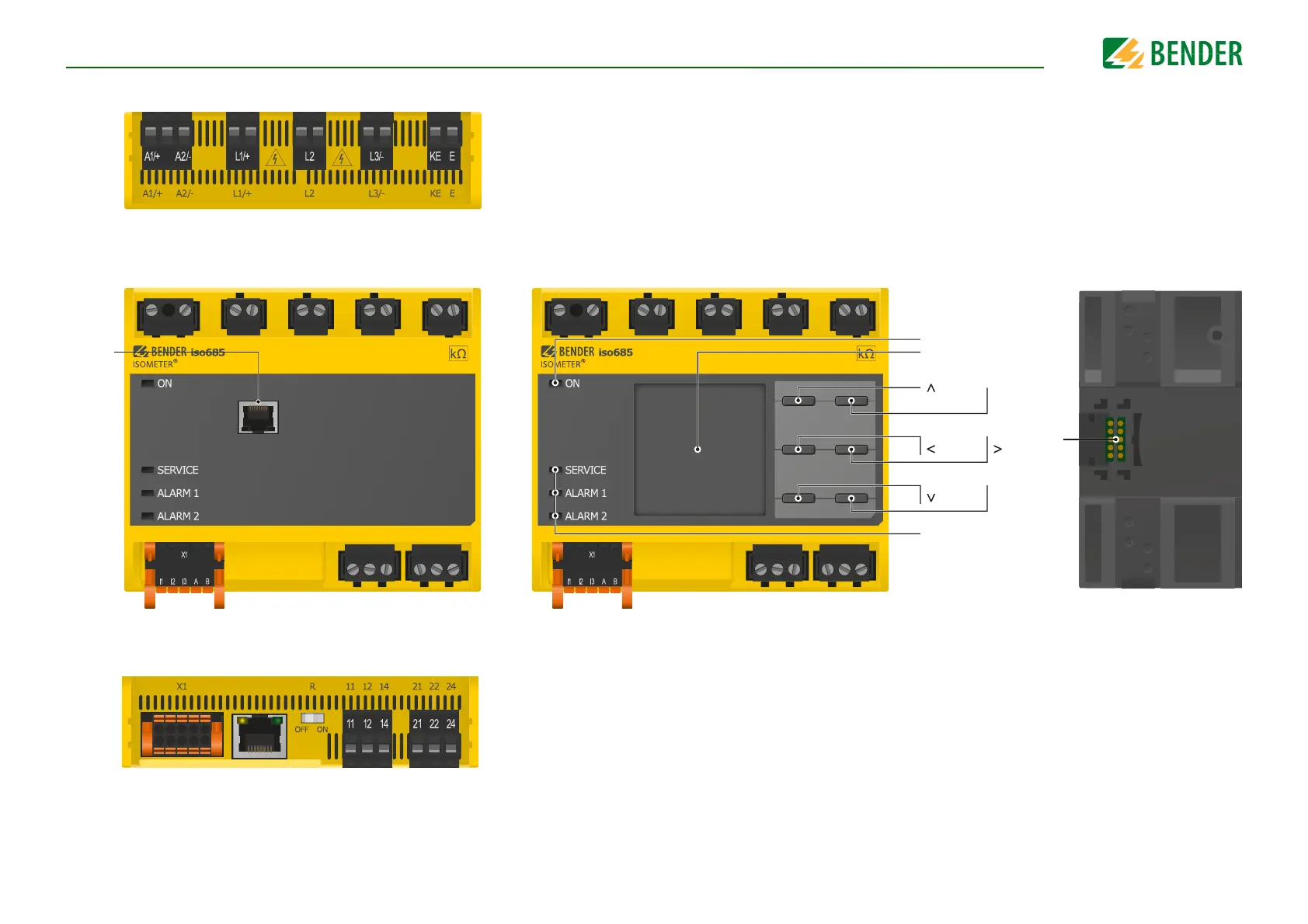
4.3 Connections and panel
A1/+, A2/- Connection to the power supply voltage U
s
L1/+ Connection to the IT system to be monitored
L2 Connection to the IT system to be monitored
L3/- Connection to the IT system to be monitored
KE, E Connection to PE
Top
ON
Display
RESET
DATA
LEDs: SERVICE,
ALARM 1, ALARM 2
MENU
ESC
TEST
INFO
OK
X3
X3 Optional expansion module for Bender devices (e. g. BB-Bus)
X4 REMOTE interface to connect to the FP200
iso685-S-B
Back
Front
X1 Digital interface
ETH Ethernet interface
R Selectable resistance R
11 12 14 Connector for alarm relay 1
21 22 24 Connector for alarm relay 2
Bottom