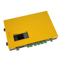
Do you have a question about the Bender Isometer IR420-D4 and is the answer not in the manual?
Guidance on how to use the manual for qualified personnel in electrical engineering.
Explains symbols for danger, warning, caution, and information for safe operation.
Visual indicators for disposal, protection from wetness, dust, temperature, and recycling.
Information on training courses, delivery conditions, and storage guidelines.
Conditions under which warranty and liability claims are excluded for personal and property damage.
Dangers of electric shock and essential safety measures before installation and connection.
Caution regarding isolating the device from the IT system during insulation or voltage tests.
Defines the intended use for monitoring insulation resistance in unearthed AC control circuits (IT systems).
Describes the device's purpose and how it generates measurement voltage to detect insulation faults.
Details the cyclic monitoring of system and earth connections for operational integrity.
Describes device behavior, alarms, and error messages upon interruption of a connecting lead.
Explains starting delay (t) and response delay (ton) for alarm signaling.
Provides the physical dimensions and measurements of the ISOMETER IR420 device.
Details the procedures for mounting the device on a DIN rail or using screw fixing.
Illustrates the wiring diagram and specifies connection types and terminal assignments.
Outlines steps for checking connections and performing functional tests before operation.
Identifies the device's buttons and their functions on the front panel.
Lists and explains the meaning of various display elements and symbols.
Provides a diagram and list of available menu items and their functions.
Explains how to set prewarning and alarm thresholds for insulation resistance.
Configure fault memory and alarm relay operation (N/O or N/C).
Adjust response value thresholds for prewarnings and alarms.
Activate, change, or deactivate password protection for the device.
Reset settings to factory defaults and adapt response values.
How to access and view the device's software version via the menu.
Comprehensive specifications for insulation coordination, supply voltage, response values, and time behavior.
Details on display range, operating uncertainty, password, and fault memory.
Information on cable length for inputs and specifications for switching elements.
Contact data per IEC 60947-5-1 and environmental/EMC classifications.
Classification of mechanical conditions and connection types/properties.
Details on operating mode, mounting, degree of protection, enclosure material, and weight.
Part numbers and specifications for ordering the IR420-D4 device and accessories.
Lists the device standards that the ISOMETER IR420 series complies with.
| Device Type | Insulation Monitoring Device |
|---|---|
| Protection Class | IP20 |
| Housing Material | Plastic |
| Standards | IEC 61557-8 |
| Resistance | 1 kΩ to 10 MΩ |
| Low-Resistance Measurement | Not supported |
| Display | LCD |
| Safety | IEC 61010-1 |
| Rated Operating Voltage | AC/DC 24…230 V |
| Response Value | 1 kΩ…10 MΩ |
| Operating Temperature | -10 °C to +55 °C |
| Mounting | DIN rail |


