Device overview
iso685-D-P_D00170_00_M_XXDE/06.2016
17
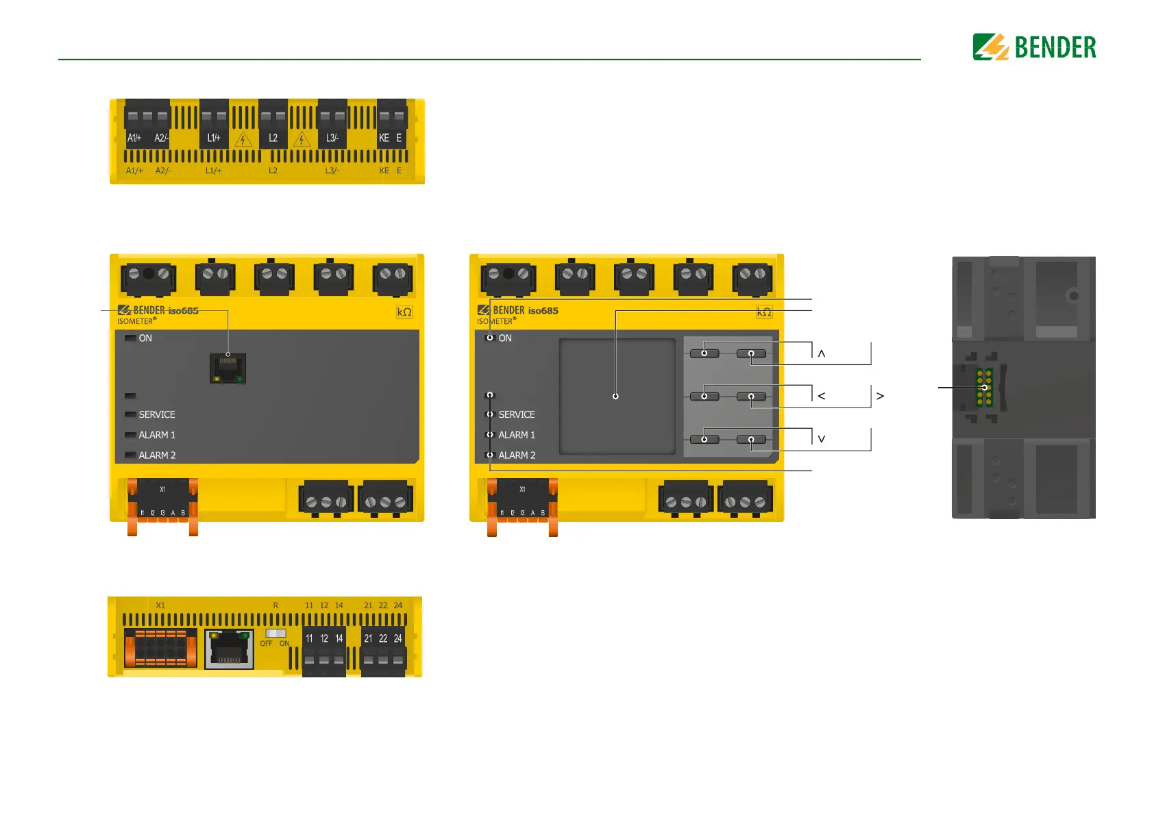
4.3 Connections and panel
A1/+, A2/- Connection to the power supply voltage U
s
L1/+ Connector for the IT system to be monitored
L2 Connector for the IT system to be monitored
L3/- Connector for the IT system to be monitored
KE, E Connection to PE
Top
PGH ON
ON
RESET
DATA
LEDs: PGH ON, SERVICE,
ALARM 1, ALARM 2
MENU
ESC
TEST
INFO
OK
X3
EDS
X3 Optional expansion module for Bender devices (e. g. BB-Bus)
X4 REMOTE interface to connect to the FP200
iso685-S-P
Back
Front
X1 Multifunctional I/O interface (refer to page 23)
ETH Ethernet interface
R Switchable terminating resistor for termination
of the RS-485 interface
11 12 14 Connector for alarm relay 1
21 22 24 Connector for alarm relay 2
Bottom