Installation, connection and commissioning
30
isoRW425_D00052_03_M_XXEN / 02.2017
4.3 Commissioning
1. Check that the ISOMETER® is properly connected to the system to be
monitored.
2. Connect the supply voltage to the ISOMETER®
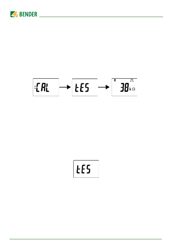
The device carries out a calibration, a self test and adjusts itself to the IT
system to be monitored. When high system leakage capacitances are
involved, this procedure may take up to 4 minutes. The standard dis-
play then appears showing the present insulation resistance, e.g.:
The pulse symbol signals an error-free update of the resistance and
capacitance measuring values. If the measuring value cannot be
updated due to disturbances, the pulse symbol will be blanked.
3. Starting a manual self test by pressing the test button "T". Whilst the
test button is pressed and held down, all display elements available for
this device are shown. During the test, the "tES" symbol flashes. Any
internal malfunctions detected are shown on the display as error codes
(Page 17). The alarm relays are not checked during the test (factory set-
ting). The setting can be changed in the "out" menu, so that the relays
switch into the alarm state during the manual self test.
4. Check factory setting for suitability
Are the settings suitable for the monitored installation?
For the list of factory settings, refer to the tables on Page 34 to Page 39.
5. Check the function using a genuine insulation fault
Check the ISOMETER® in the system being monitored against earth, e.g.
via a suitable ressistance.