Installation, connection and commissioning
29
isoRW425_D00052_03_M_XXEN / 02.2017
For details about the conductor cross sections required for wiring, refer to the
technical data on Page 67.
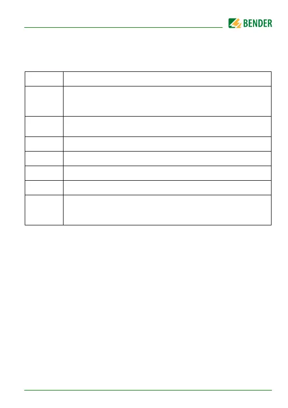
Wiring diagram legend:
Termi na l Con ne cti ons
A1, A2
Connection to the supply voltage via fuse (line protection).
If supplied from an IT system, both lines have to be protected
by a fuse.
E, KE
Connect each terminal separately to PE:
The same wire cross section as for A1, A2 is to be used.
L1/+, L2/–
Connection to the 3(N)AC, AC or DC system to be monitored
T/R
Connection for the external combined test and reset button.
11, 14
Connection to alarm relay K1
11, 24
Connection to alarm relay K2
A, B
RS-485 communication interface with connectable terminating
resistance.
Example: Connection of a BMS-Ethernet-Gateway COM460IP