Device operation
40
isoRW425_D00052_03_M_XXEN / 02.2017
5.7 Measuring value display and history memory
In R mode only R
F
and in Z mode only Z
F
is permanently shown on the display
(standard display). All other measuring value displays switch to the standard
display after a maximum of 5 minutes. The fault location will only be stored in
the history memory (HiS) in R mode. In Z mode only will Z
F
be stored in the his-
tory memory. The pulse symbol indicates a current measured value. If this
symbol does not appear, the measurement is still running and the latest valid
measured value will be displayed. The symbols < or > will be displayed addi-
tionally to the measured value when a response value has been reached or vi-
olated, or the measured value is below or above the measuring range.
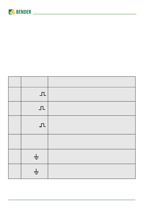
HiS Display Description
Z k
Insulation impedance Z
F
1 k ... 1 M Resolution 1 k
± R k
Insulation resistance R
F
1 k ... 4 M Resolution 1 k / 10 k
C µF
Leakage capacitance C
e
Z mode = off: 1 µF … 300 µF Resolution 1 µF
Z mode = on: 1 nF … 1 µF Resolution 1 nF
~ ± U L1 L2 V
Mains voltage L1 - L2 U
n
0 V
rms
… 500 V
rms
Resolution 1 V
rms
± U L1 = V
Mains voltage L1/+ - PE U
L1e
0 V
DC
… 500 V
DC
Resolution 1 V
DC
± U L2 = V
Mains voltage L2/- - PE U
L2e
0 V
DC
… 500 V
DC
Resolution 1 V
DC