Modbus register assignment of the ISOMETER®
56
isoRW425_D00052_03_M_XXEN / 02.2017
8.1 Device-specific data type of the ISOMETER®
8.1.1 Device name
The data format of the device name is specified below.
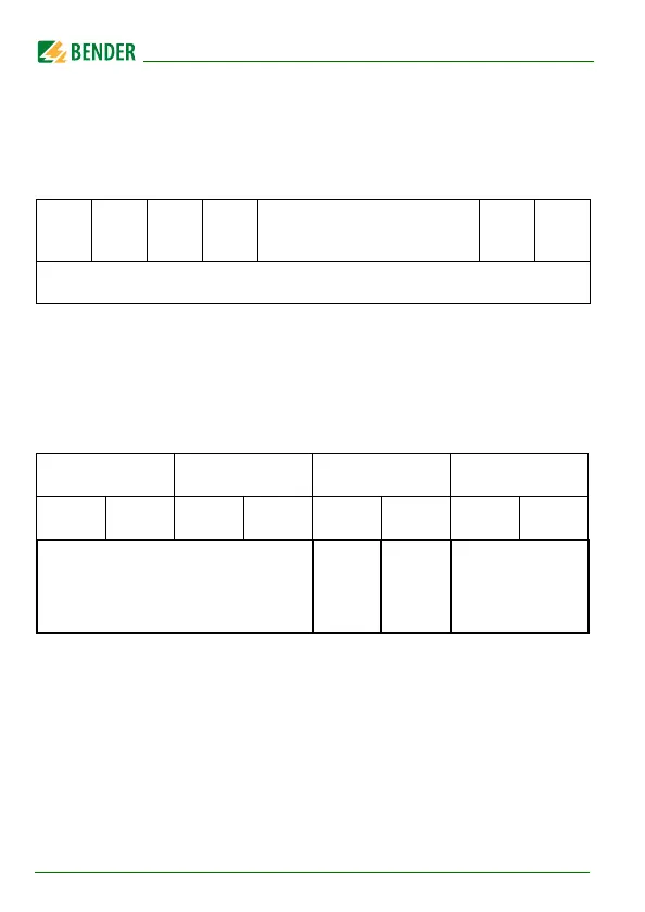
8.1.2 Measuring values
Each measuring value is available as a channel and consists of 8 bytes (4 reg-
isters). The first measuring value register address is 1000. The structure of a
channel is always identical. Content and number depend on the device. The
structure of a channel is shown with the example of channel 1:
Word
0x00
0x01 0x02 0x03 ------------------- 0x08 0x09
10 Words in total
Each Word contains two ASCII characters
1000 1001 1002 1003
HiByte LoByte HiByte LoByte HiByte LoByte HiByte LoByte
Floating point value (Float)
Alarm
type and
test type
(AT&T)
Range
and unit
(R&U)
Channel
description