Operation of the device
37
isoPV425_D00028_09_M_XXEN/05.2018
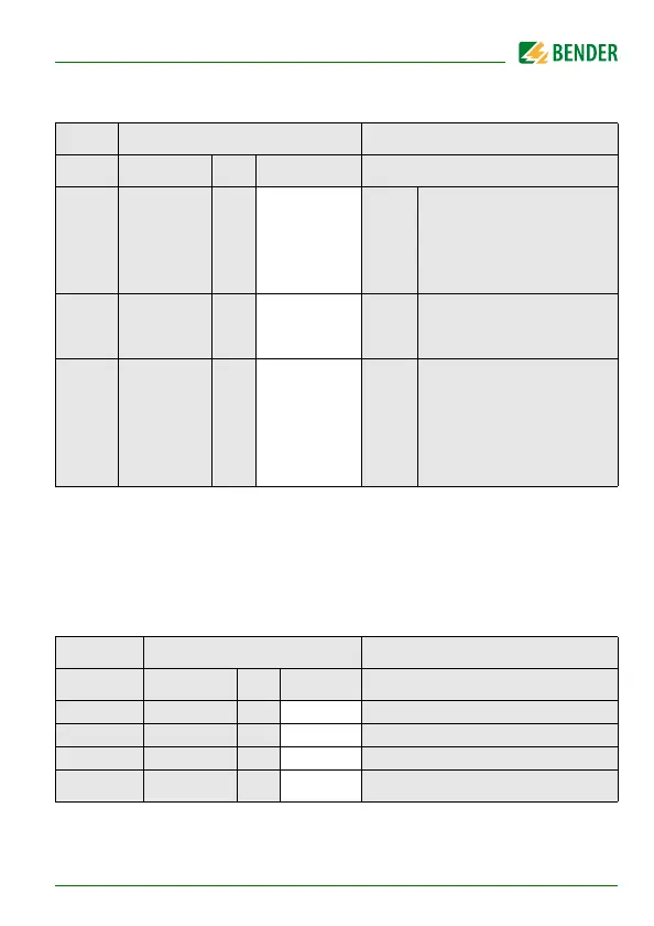
5.4.4 Interface configuration
FAC = Factory setting; Cs = User settings
( ) = User setting that is not modified by FAC.
5.5 Menu "t"
5.5.1 Time configuration
FAC = Factory setting; Cs = User settings
Display Setting value Description
Value range FAC Cs
Adr 0 / 3 … 90 3 ( )
Bus
adr.
Adr = 0 deactivates BMS as
well as Modbus and acti-
vates isoData with continu-
ous data output
(115k2, 8E1)
Adr 1
--- /
1.2k … 115k
“---“ ( )
Baud
rate
“---“ : BMS bus (9k6, 7E1)
"1.2k" … "115k" -->
Modbus (variable, variable)
Adr 2
8E1
8o1
8n1
8E1 ( )
Modbus
8E1 - 8 data bits
even parity, 1 stop bit
8o1 - 8 data bits
odd parity, 1 stop bit
8n1 - 8 data bits
no parity, 1 stop bit
Display Setting value Description
Value range FAC Cs
t 0 … 10 0 s Device start-up delay
ton 0 … 99 0 s Response delay K1 and K2
toff 0 … 99 0 s Delay on release K1 and K2
test
OFF / 1 / 24
24 h Repetition time device test