Operation of the device
38
isoPV425_D00028_09_M_XXEN/05.2018
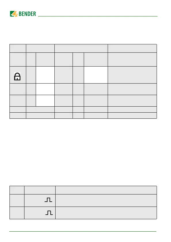
5.6 Menu "SEt"
5.6.1 Function configuration
FAC = Factory setting; Cs = User settings
5.7 Measuring value display and history memory
All other measuring value displays switch to the standard display (insulation
resistance) after a maximum of 5 min. The pulse symbol indicates the current
measured value. If this symbol does not appear, then the measurement is still
running and the latest valid measured value will be displayed. The symbols
"<" or ">" will additionally be displayed with the measured value when a re-
sponse value has been reached or exceeded, or the measured value is below
or above the measuring range.
Display Activation Settings Description
FAC Cs
Value
range
FAC
Cs
off 0 . . . 999
0
Password for
parameter setting
nEt on
Monitoring system con-
nection during device test
S.Ct
on
Device test during device
start
FAC Restore factory settings
SYS For Bender Service only
HiS Display Description
± R kΩ
Insulation resistance R
F
1 kΩ …1 MΩ Resolution 1 kΩ
C µF
System leakage capacitance C
e
1 µF … 1105 µF Resolution 1 µF