Operation of the device
39
isoPV425_D00028_09_M_XXEN/05.2018
: The measured value can be displayed in the history memory.
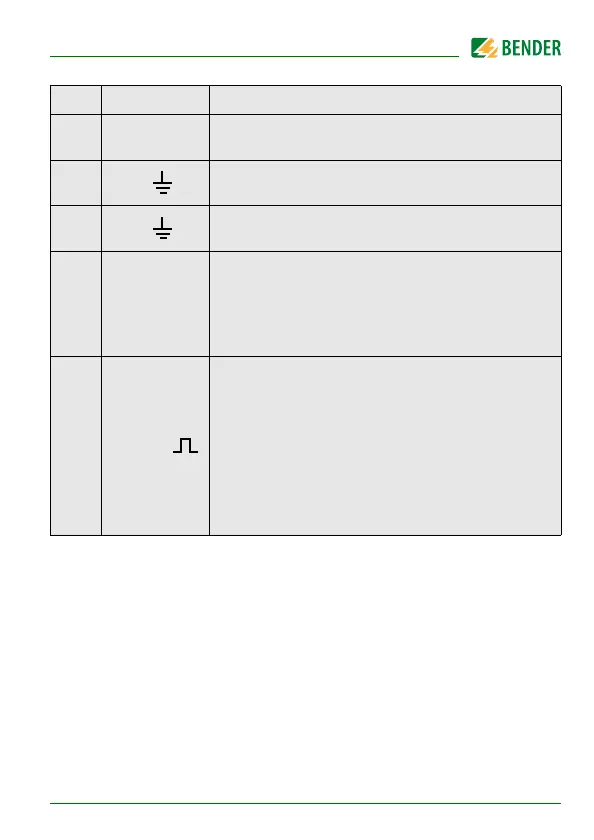
~ ± U L1 L2 V
Nominal system voltage L1 - L2 U
n
0 V
RMS
… 1.20 kV
RMS
Resolution 1 V
RMS
/ 10 V
RMS
± U L1 = V
Residual voltage L1/+ - PE U
L1e
0 V
DC
… ±1.20 kV
DC
Resolution 1 V
DC
/ 10 V
DC
± U L2 = V
Residual voltage L2/- - PE U
L2e
0 V
DC
… ±1.20 kV
DC
Resolution 1 V
DC
/ 10 V
DC
± R %
Fault location in %
-100 % …+100 %
Indication only from U
n
≥ 100 V
DC
R
L1F
= (200 % * R
F
) / (100 % + x %)
R
L2F
= (200 % * R
F
) / (100 % - x %)
-
U R = kΩ
Insulation resistance R
UGF
1 kΩ … 1 MΩ Resolution 1 kΩ
R
UGF
is an approximate value for asymmetrical insula-
tion faults and can be used as a trend indicator with
short measuring times. It is determined by the DC mains
voltage ( > 50 V ) and is only correct in the event of one-
sided insulation faults. If there are simultaneous insula-
tion faults at L1/+ and L2/- the value is indicated as a too
high impedance.
HiS Display Description