Function
12
TGH1361en/11.2009
2.3 Product description
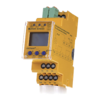
The A-ISOMETER® type IRDH275 monitors the insulation resistance of IT
systems. It is suitable for universal use in 3(N)AC, AC/DC and DC systems.
AC systems may include extensive DC supplied loads, such as converters or
thyristor-controlled DC drives. The device automatically adapts itself to the
existing system leakage capacitance.
Suitable coupling devices are available to extend the nominal voltage range
U
n
.
The IRDH275B can be used in combination with a control and indicating de-
vice, e.g. PRC1470 version 2 or higher, on the BMS (BMS = Bender Measur-
ing Device Interface) bus.
2.4 Function
The A-ISOMETER® IRDH275 is connected between the unearthed system (IT
system) and the protective conductor (PE).
The response values and other function parameters are set via the function
keys. The parameters are indicated on the LC display and are stored in a non-
volatile memory (EEPROM) after the setting is completed.
A microprocessor-controlled pulsating AC measuring voltage is superim-
posed on the IT system to be monitored ( measuring principle*). The
measuring cycle consists of positive and negative pulses of the same ampli-
tude. The period of these pulses depends on the respective system leakage
capacitances and the insulation resistances of the IT system to be monitored.
An insulation fault between the IT system and earth closes the measuring cir-
cuit. From the measured current value, the microprocessor calculates the in-
sulation resistance which is indicated on the LC display or the external kΩ
measuring instrument.
The measuring time is determined by the system leakage capacitances, the
insulation resistance, and the system-related interference disturbances. Sys-
tem leakage capacitances do not influence the measuring accuracy.
If the reading is below the selected response values Alarm 1/Alarm 2, the as-
sociated alarm relays respond and the alarm LEDs "Alarm 1/2“ light up and
the measuring value is indicated on the LC display (in the event of DC insu-
lation faults, the faulty supply line is indicated). If the terminals R1/R2 are
bridged (external RESET button [NC contact] or wire bridge), the fault indi-
cation will be stored. Pressing the RESET button, resets the insulation fault

 Loading...


