Connection
28
TGH1361en/11.2009
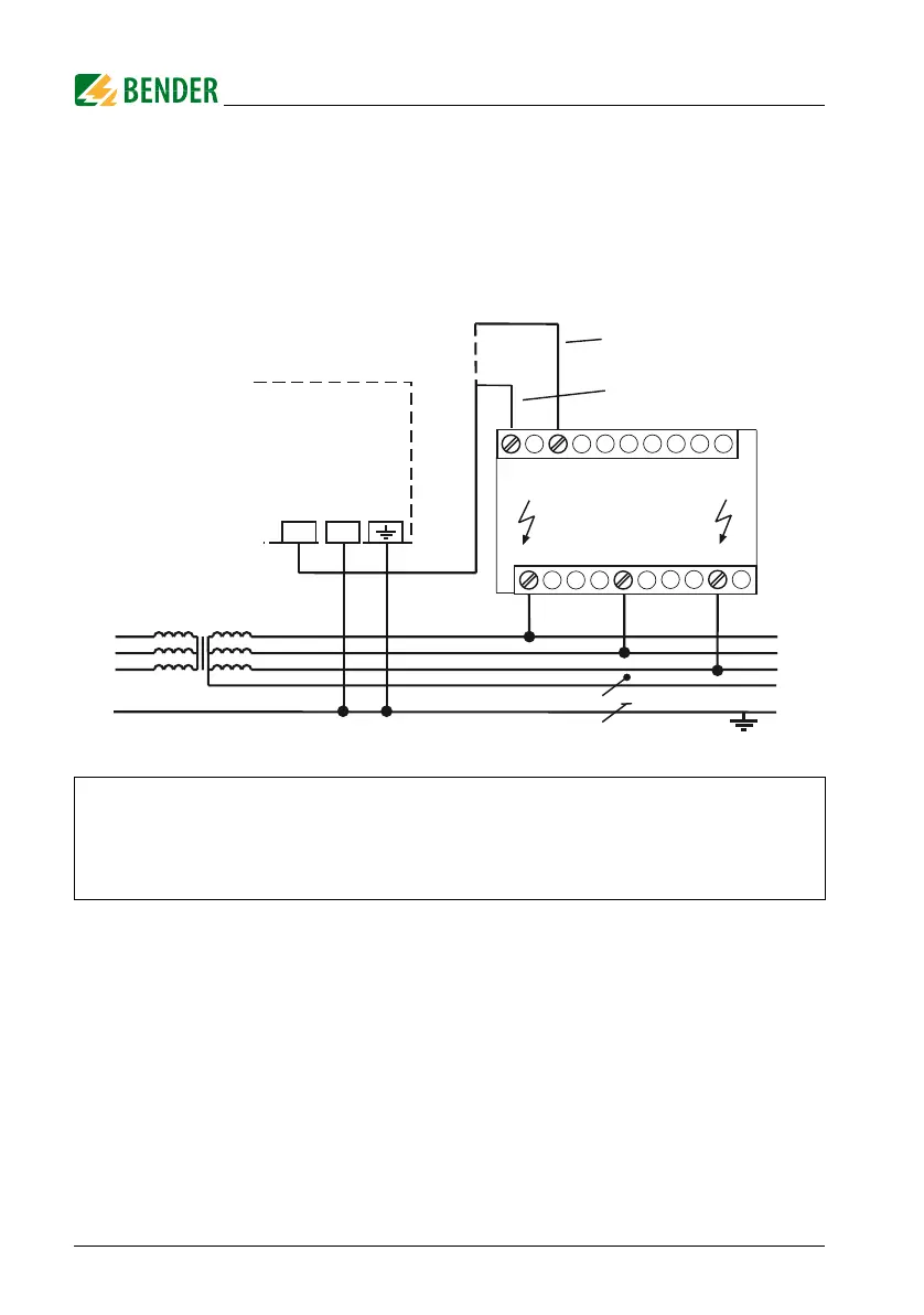
4.2.3 Connection with AGH204S-4
This coupling device extends the nominal voltage range of A-ISOMETERs®
used in AC systems including rectifiers.
The maximum DC voltage is the voltage permitted to occur in the AC part of
an IT system to PE when the IRDH275 is coupled with AGH204S-4 in this
part of the system. This voltage is dependent on the level of the nominal volt-
age, the type of rectification 6 pulse, 12 pulse,...), the type of converter in-
termediate circuit (current... or voltage...), and the converter technology. In
case of converters, the maximum DC voltage in the intermediate circuit usu-
ally corresponds to the phase-to-phase voltage of the supplying AC system
multiplied by 1.414.
1 without rectifiers
U
n
= 3AC 0....1650 V (DC max. 1000 V)
2 with rectifiers
U
n
= 3AC 0....1300 V (max. AC voltage; max. DC voltage
after rectifiers in intermediate circuits of frequency con-
verters:1840 V)
L1
L2
L3
PE
Un
N
AGH204S-4
1
2
AK160
AK80
U3
V3
W3
IRDH275
KE
AK
 Loading...


