Serial interfaces
57
TGH1361en/11.2009
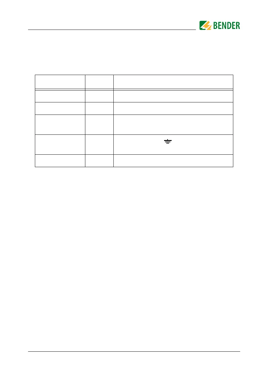
The following table gives an overview about essential alarm messages and
the assignment of the messages indicated on the display or operator panels,
e.g. PRC1470.
The BMS function is completely available in the standby mode (Stand-by: F1/
F2).
6.4.3 Commissioning of an RS485 network with BMS protocol
z Connect the terminals A and B of all bus nodes in one line
z Switch the terminating resistors on at the beginning and end of the RS485
network or in case of devices without a terminating switch, at the end of the
bus, connect a 120 Ω resistor to the terminals A and B.
z Switch the supply voltage U
S
on.
z Determine one IRDH275 as the Master and assign address 1.
z Assign the addresses (2...30) subsequently to all other IRDH275B devices and
other bus nodes (see table below).
z Check whether a flashing point appears on all devices
(BMS commands are being received).
z The sub menu "ISO-Monitor" in the COM SETUP menu allows insulation values
of the A-ISOMETERs® to be queried. Before starting the query, the
address of the A-ISOMETER® has to be entered.
Message
Channel
Meaning
Insulation Fault
1
Insulation resistance < setting Alarm 1
Insulation Fault
2
Insulation resistance < setting Alarm 2
Connection sys-
tem
3
Connection error L1/L2 against system
Connection PE
4
Connection error /KE against PE con-
ductor
Device error
5
Internal device error
 Loading...


