Control System Components
(4
Inch Instruments:
SENSE CONTROL COMPUTE DISPLAY
AIP
DiscITrim
Manual
Electric
Interrupt
Switch
CWS Switch
Control Wheel
Switches
Throttle
Go-Around
I
9
II
KPI
552
r?
KEA 346
Servoed
Altimeter
ta
KAS
297
AH
Pre-Select
Monitor
1 1
I
Switch
Pitch
Yaw
Roll
Pitch
Trim
KA
518
KMT
112
ServolMount
ServolMount ServolMount ServolMount
KFC
250
System Integration
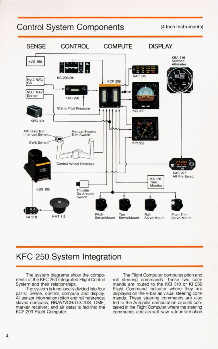
The system diagrams show the compo-
nents of the KFC 250 Integrated Flight Control
System and their relationships.
The system is functionally divided into four
parts: Sense, control, compute and display.
All sensor information (pitch and roll reference:
slaved compass: RNAVIVORILOCIGS;
DME:
marker receiver: and air data) is fed into the
KCP 299 Flight Computer.
The Flight Computer computes pitch and
roll steering commands. These
two
com-
mands are routed to the KCI
310
or KI 256
Flight Command Indicator where they are
displayed on the V-bar as visual steering com-
mands. These steering commands are also
fed
to
the Autopilot computation circuits con-
tained in the Flight Computer where the steering
commands and aircraft yaw rate information
I..
F.
-...:
*
.
._
?
I.
,-.
,
...
.
..
I.
I'
'A
;
,
*'
.