35
Troubleshooting Diagnostic Trouble Codes:
Yaw Rate Sensor (YRS) (continued)
Yaw Rate Sensor Tests
1. Measure resistance between input voltage and ground
at the sensor wiring harness connector.
Test Measurement
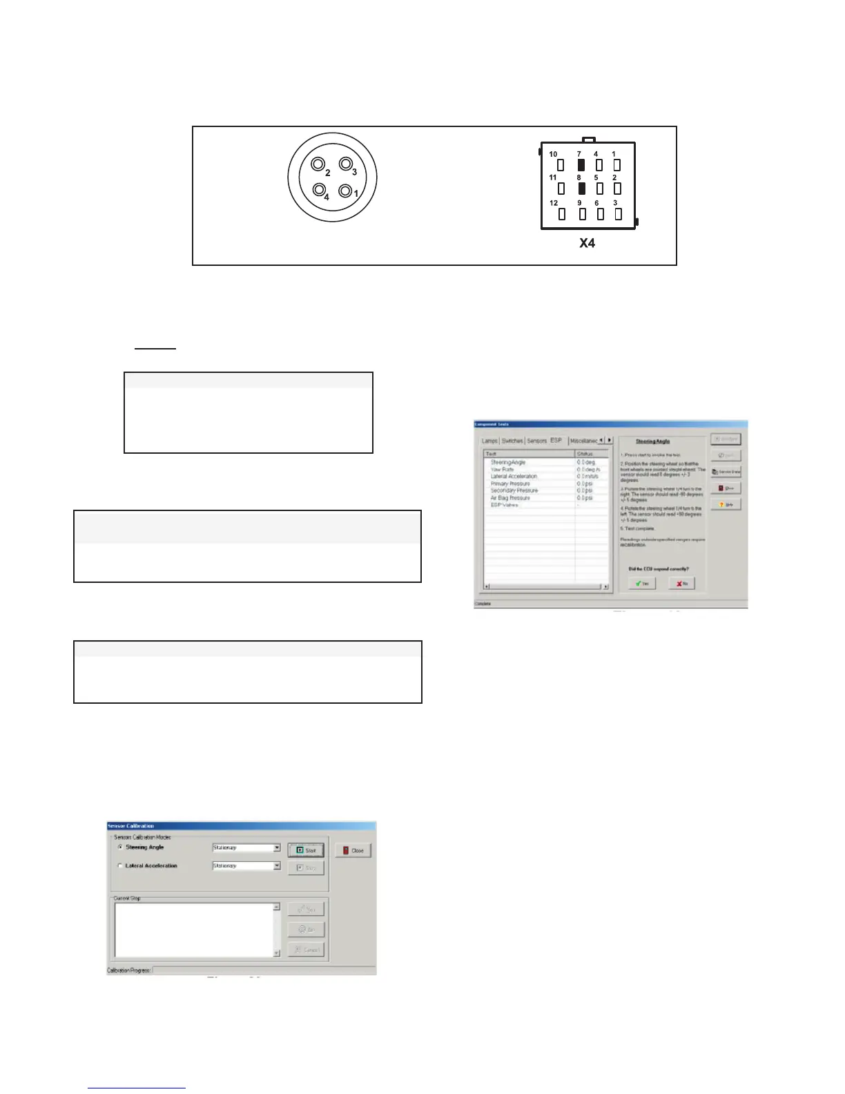
Power and Ground Input 8 to 16 volts
1 = Power Input
2 = Ground Input
2. Verify wiring between the Yaw Rate Sensor and the
ECU.
SAS Wire Harness ECU Wire Measurement
Terminal Harness Terminal
4 7 Verify Continuity
3 8 Verify Continuity
Looking into wire harness connector
3. Verify wiring between the Yaw Rate Sensor and power/
ground.
SAS Wire Harness Terminal Measurement
4 to Voltage & Ground Verify open circuit (no continuity)
3 to Voltage & Ground Verify open circuit (no continuity)
4. To perform a calibration procedure of the Yaw Rate
Sensor, ACom
™
Diagnostics V4.0 is required. Using
the program, select the “Configuration” option, followed
by the “Calibrate” option. The following screen should
be displayed.
5. Follow the prompts to perform a calibration of the Yaw
Rate Sensor.
6. To test the Yaw Rate Sensor, ACom V4.0 is required.
Using Bendix ACom V4.0, select the “Component Test”
option, followed by the “ESP Test” option. The following
screen should be displayed.
7. Follow the prompts to perform a test of the Yaw Rate
Sensor.