23
Troubleshooting Diagnostic Trouble Codes: Power Supply
6 Power Supply
1st. Blink
Code
Location
2nd. Diagnostic
Blink Trouble Code
Code Description
1 Battery Voltage
Too Low
2 Battery Voltage
Too High
3 Battery Voltage
Too Low
During ABS
4 Battery Voltage
Open Circuit
5 Ignition Voltage
Too Low
6 Ignition Voltage
Too High
7 Ignition Voltage Too
Low During ABS
8 Input Voltage Has
Excessive Noise
(Temporary)
9 Input Voltage Has
Excessive Noise
Measure battery voltage under load. Check vehicle battery and associated components.
Check for damaged wiring. Check for damaged or corroded connectors and connections.
Measure battery voltage under load. Insure that battery voltage is correct for the model of
ECU. Check vehicle battery and associated components. Check for damaged wiring.
Check for damaged or corroded connectors and connections.
Measure battery voltage under load. Check vehicle battery and associated components.
Check for damaged wiring. Check for damaged or corroded connectors and connections.
Measure battery voltage under load. Check condition of fuse. Check vehicle battery and
associated components. Check for damaged wiring. Check for damaged or corroded
connectors and connections.
Measure ignition voltage under load. Check vehicle battery and associated components.
Check for damaged wiring. Check for damaged or corroded connectors and connections.
Check condition of fuse.
Measure ignition voltage. Insure that ignition voltage is correct for the model of ECU.
Check vehicle battery and associated components. Check for damaged wiring. Check
for damaged or corroded connectors and connections.
Measure ignition voltage under load. Check vehicle battery and associated components.
Check for damaged wiring. Check for damaged or corroded connectors and connections.
Check alternator output for excessive noise. Check for other devices causing excessive
noise.
Check alternator output for excessive noise. Check for other devices causing excessive
noise.
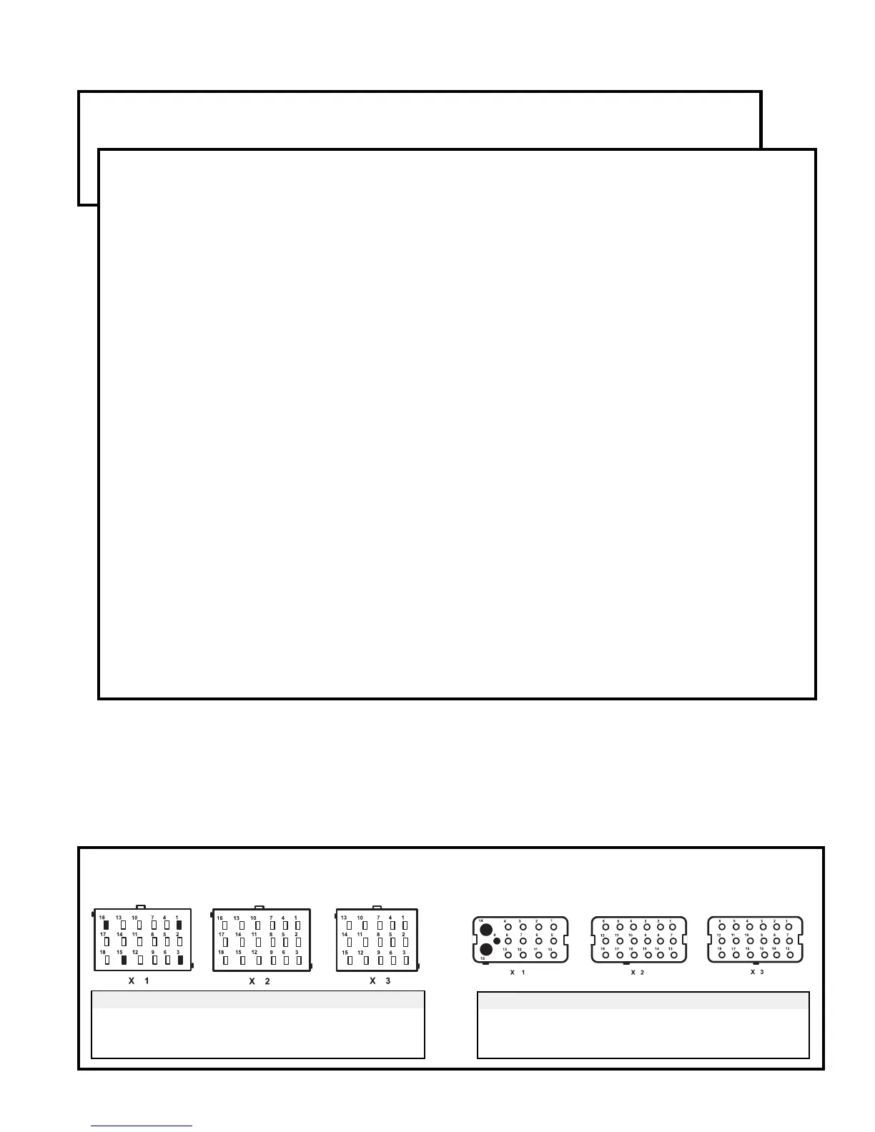
Repair Information
Frame-mount ECU:
Looking into wire harness connector
Power Supply Tests:
1. Take all measurements at ECU harness connector.
2. Place a load (e.g. an 1157 stop lamp) across battery
or ignition and ground connection, measure ignition
and battery voltage with the load. Ignition to Ground
should measure between 9 to 17 VDC. Battery to
Ground should also measure between 9 to 17 VDC.
3. Check for damaged wiring, damaged or corroded
connectors and connections.
4. Check condition of vehicle battery and associated
components, ground connection good and tight.
5. Check alternator output for excessive noise.
Connector Pin Power Supply Test
X1 1 Ground
18 Way 3 Ignition
16 Battery
Connector Pin Power Supply Test
X1 9 Ignition
15 Way 14 Battery
15 Ground
Cab-mount ECU:
Looking into wire harness connector