1
Bendix
®
QR-N
™
Quick Release Valve
SD-03-905
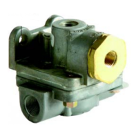
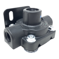
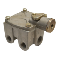
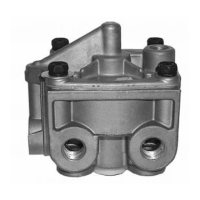
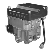
MOUNTING HOLE (2)
SUPPLY PORT
FIGURE 1
EXHAUST PORT
DELIVERY
PORT
DESCRIPTION
The function of the Bendix
®
QR-N
™
quick release valve is to
“speed up” the exhaust of air from the actuators it serves. It
is generally mounted on the vehicle axle midway between
the two actuators connected to it.
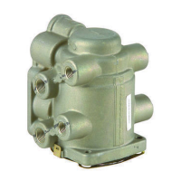
In the standard (Refer to Figure 1) QR-N
™
valve a fl at
circular diaphragm is installed between the nonmetallic
upper body and stamped steel lower body. An o-ring seals
the two body halves which are held together using four 1/4"
machine screws and fl ange nuts.
In its standard confi guration the QR-N
™
valve is supplied
with a 1 psi (6.9 kPa) maximum differential. For example
with supply pressure at 10 psi (68.9 kPa) delivery pressure
is 9 psi (61.8 kPa). Higher differential pressures are
available for special applications and are obtained by the
addition of a spring and diaphragm follower to the standard
QR-N
™
valve (Refer to Insert A).
Various pipe thread sizes are available for the single supply
port and two delivery ports of the QR-N
™
valve. QR-N
™
valve mounting is accomplished via two 11/32" diameter
holes on 1-1/2" centers.
OPERATION
With no air pressure applied to the QR-N
™
valve (Refer
to Figure 1), the diaphragm is slightly fl exed by the upper
and lower body. In this condition the center portion of the
diaphragm rests on the exhaust port in the lower body while
the outer edge and opposite side of the diaphragm rests
against the sealing lip of the upper body.
APPLY
Air entering the supply port of the QR-N
™
valve causes the
center portion of the diaphragm to seal the exhaust port.
Simultaneously, the outer edge of the diaphragm moves
away from the sealing lip of the upper body allowing air to
fl ow from the supply port out the delivery ports.
BALANCE
When air pressure on both sides of the diaphragm
is approximately equal (1 psi differential), the natural
resiliency of the diaphragm material causes the outer
edge of the diaphragm to move into contact with the upper
body sealing lip. The QR-N
™
valve exhaust remains sealed
because air pressure bears against the center portion of
the diaphragm from one side only.
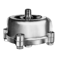
UPPER BODY
DELIVERY
PORT
SEALING RING
LOCKWASHER
CAP SCREW
SPRING FOLLOWER
DIFFERENTIAL SPRING
LOWER
BODY
INSERT A
DIAPHRAGM