12
PRESSURE SENSOR, COVER,
AND GASKET REPLACEMENT
If a pressure sensor has been identified as faulty or
damaged, it must be replaced. (A service kit is available
from R.H. Sheppard.) Once the faulty or damaged
pressure sensor is removed, follow the steps below for the
installation of the new sensor.
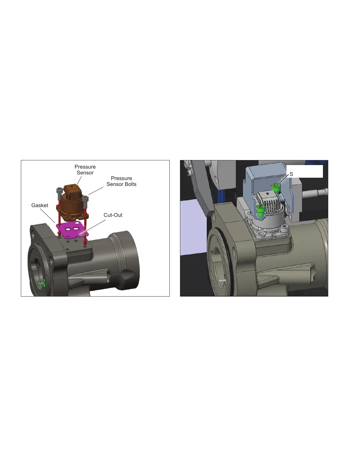
1. Align the gasket and pressure sensor with the half circle
cut-out in each part. See Figure 10.
2. Align the pressure sensor and gasket on the bearing
cap. See Figure 10.
3. Hand start and torque the front right, and back left
pressure sensor bolts to 13-16 ft-lb (17.6-21.7 Nm) with
the 5 mm hex (Allen
®
) bit. See Figure 10.
Figure 10 – Pressure Sensor and Gasket Figure 11 – Bolt Installation
Gasket
Pressure
Sensor
Pressure
Sensor Bolts
Cut-Out
Pressure
Sensor Bolts
Magnetic Torque
Overlay Steering
Gear
4. Remove the alignment xture (if used) and install the
pressure sensor cover by aligning the bottom tabs with
the open bolt holes. See Figure 11.
5. Hand start and torque the front left and back right bolts
to 13-16 ft-lb (17.6-21.7 Nm) through the tabs of the
pressure sensor cover with the 5 mm hex (Allen) bit.
See Figure 11.
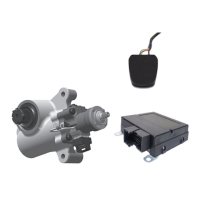
MAGNETIC TORQUE OVERLAY
STEERING GEAR AND ECU
REPLACEMENT
To replace the steering gear or the ECU, please contact
the Bendix
®
Tech Team or Sheppard
®
Technical Support.
See page 13.