21
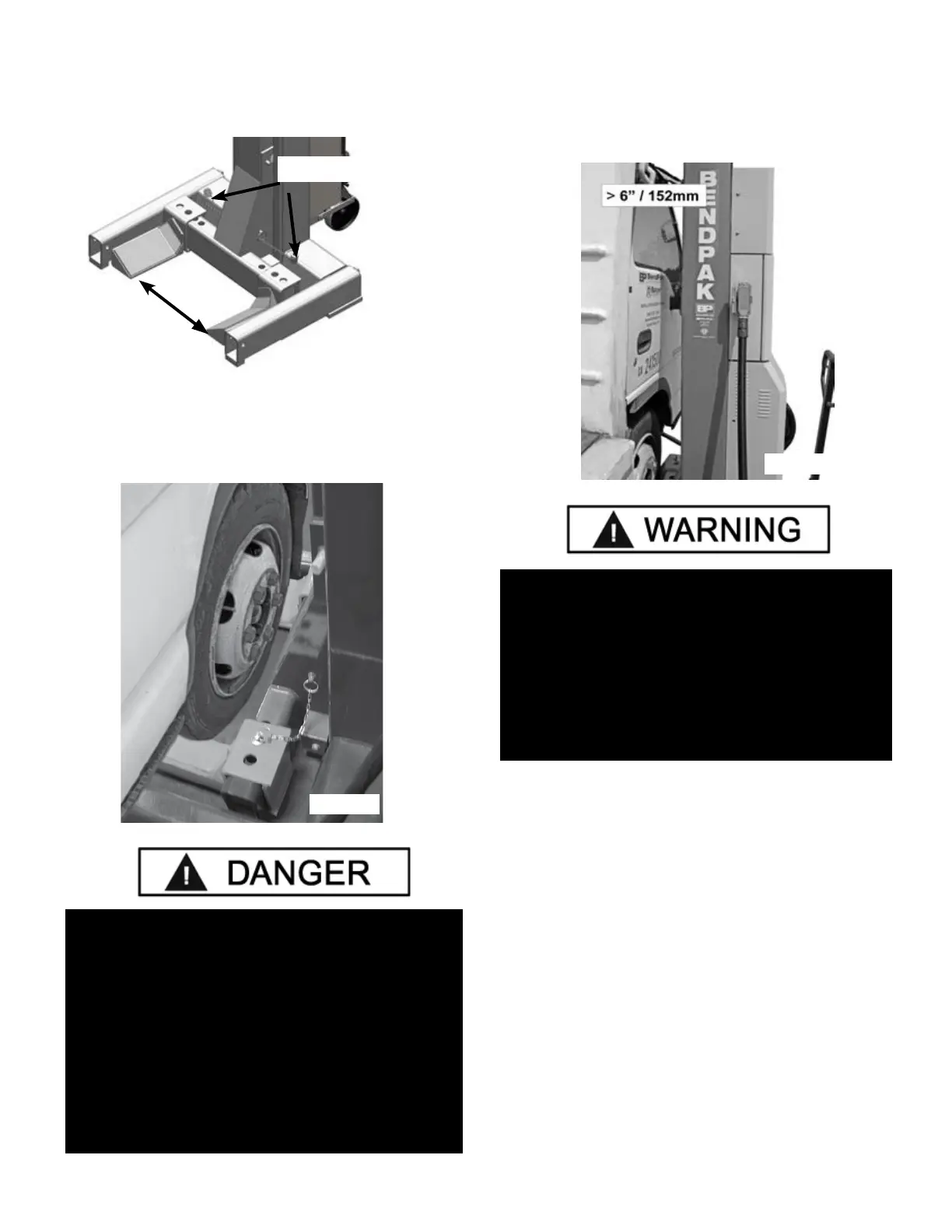
4. Adjust the fork arms by removing the Arm Locking
Pins and sliding the fork arms so that they are spaced
wider than the tire diameter of the vehicle. (See Fig 10.1)
5. Using the Hydraulic Jacking System, position each
Column so that the forks of the lift are positioned properly
around each of the vehicles wheels. The wheels should
be centered between the forks. (See Fig 10.2)
6. Lower the Column and adjust the fork arms by
pushing the arms until they touch or are as close to the
tire as possible. The lift should be parallel to the vehicle
body without touching the body or other components of
the vehicle. (See Fig 10.3)
7. When all the Columns are properly positioned and
the clearances around and above the vehicle are
clear of obstructions, the Columns can be connected.
8. Keep the Communication Cables clear of sharp
objects and foot paths. DO NOT drive over
communication cables.
9. Make sure the main Power Switch is in the “OFF”
Position.
11. Connect the Master Column to the Power source.
Connect Columns to each other. Refer to Section 6 for
communication cable routing.
WHEN LOWERING THE LIFT PAY CAREFUL
ATTENTION THAT ALL PERSONNEL AND OBJECTS
ARE KEPT CLEAR. ALWAYS KEEP A VISUAL LINE
OF SITE ON THE LIFT AT ALL TIMES. ALWAYS
MAKE SURE THAT ALL LOCKS ARE DISENGAGED.
IF ONE OF THE LOCKS INADVERTENTLY LOCKS
UPON DESCENT THE VEHICLE MAY DISMOUNT
CAUSING PERSONAL INJURY OR DEATH.
CONFIRM THAT ALL PRIMARY SAFETY LOCKS
ARE ENGAGED BEFORE ENTERING WORK
AREA. CYLINDER COMPONENTS USED ON THIS
LIFT ARE INTENDED TO RAISE AND LOWER
LIFT ONLY AND ARE NOT MEANT TO BE LOAD
HOLDING DEVICES. REMAIN CLEAR OF ELEVATED
LIFT UNLESS CONFIRMATION IS MADE THAT ALL
PRIMARY SAFETY LOCKS ARE FULLY ENGAGED
AND THE LIFT IS LOWERED ONTO THE SAFETY
LOCKS, REFER TO INSTALLATION / OPERATION
MANUAL FOR PROPER SAFETY.
Fig. 10.1
Arm Locking Pins
Fig. 10.2
Fig. 10.3
 Loading...