15
SECTION 7
CONTROL PANELS
The PCL-18B includes one Master Column (Column A) and Slave Columns (Columns B, C and D). Each Column has a
control panel that can operate in SINGLE Mode, the main Column and the one directly across from it in PAIR Mode or
all 4 Columns at once in TEAM Mode.
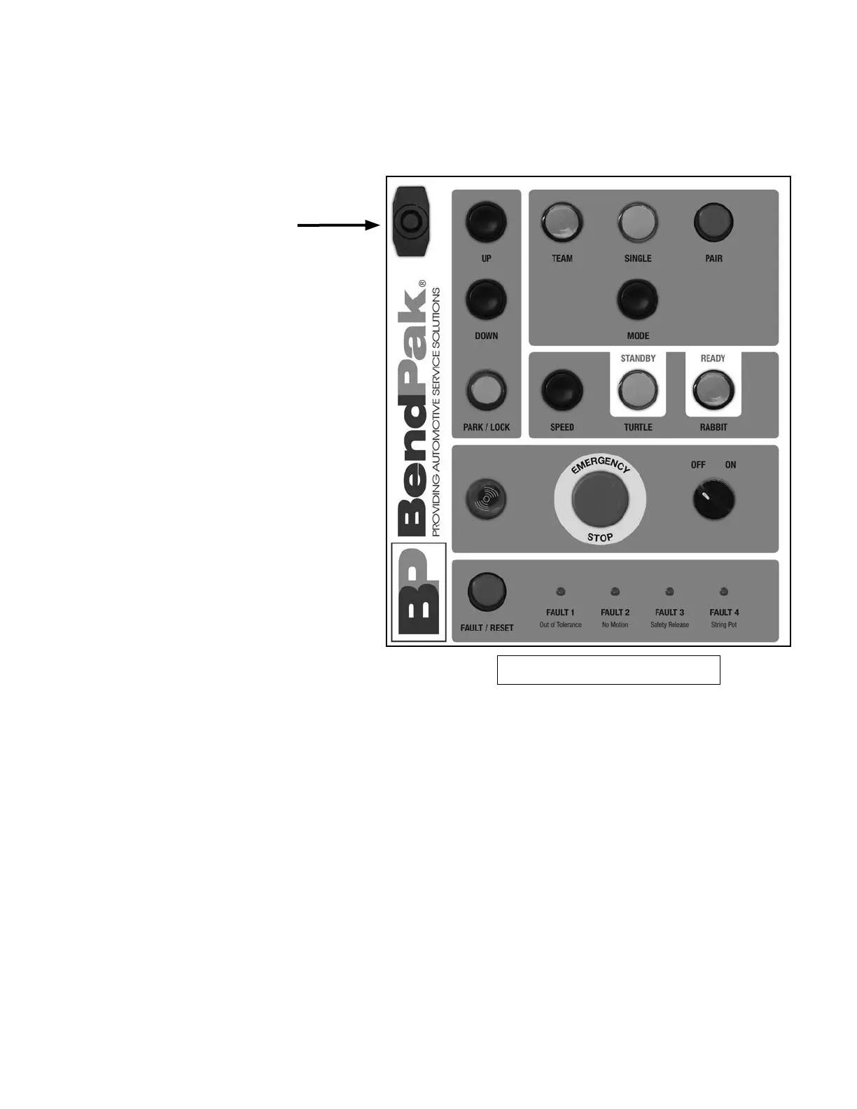
Master Column Control Panel
1. Door Lock - Prevents unauthorized
access to the circuitry of the PCL-18B
system. Make sure door is securely
closed and locked while the lift is in
operation or the columns are being
moved. Be sure if the keys are removed
that they are kept in a safe place.
2. UP Control - Initiates de lift rise
sequence.
3. DOWN Control - Initiates the lift
lowering sequence.
4. PARK Control - Initiates the lift
locking (parking) sequence. Each lift
column will slowly settle onto the
mechanical stops.
5,6,7. TEAM, SINGLE or PAIR LIGHTS
Shows which lift columns will operate
as group, tandem or individually.
8. MODE Control - Commands
specic lift columns to operate as
single, team and/or pair modes.
9. SPEED Control - Selects the
parking or lowering speeds.
10. STANDBY/TURTLE - Choose this
command for a slower “turtle” speed
and a safe controlled descent.
11. READY/RABBIT - Select the faster
“rabbit” speed for a rapid controlled
descent.
12. VISUAL/AUDIBLE ALARM - When
the Main Power switch is moved to the
“ON” position, this light will illuminate
and the alarm will sound and ash. This
alarm will activate whenever the lift is
in motion or a fault is detected in the
system.
13. EMERGENCY STOP BUTTON - Each Column has an Emergency
Stop Button. Press this button on any of the Columns when you need to
stop operation immediately. To Reset, twist button clockwise. The button
will pop back out.
14. MAIN POWER SWITCH - Controls power to all of the
Columns. When this switch is in the “OFF” position, the lift system is
powered off and not operable. When this switch is in the “ON” position,
the lift system is powered on and prepared for operation.
15. FAULT / RESET - If for any reason the lift operation exceeds a
specied out of level tolerance treshold, all lift columns will stop and
display the error as: FAULT 1: Out of Tolerance; FAULT 2: No Motion;
FAULT 3: Safety Release; FAULT 4: String Pot.
To clear the error, an ofending lift will be put in SINGLE mode and raised
or lowered accordingly to reduce the difference in lift heights.
16. CALIBRATION BUTTON - Press and hold this button and in ve
seconds the calibration procedure will be completed.