24
• To prevent damage to the column control panels,
avoid touching the outside and inside of the box panel
with sharp objects, striking the panel with a hard object,
the use of abrasives or using excessive force when
pressing the ergonomic push-button controls. In the
event that any of the components stop working correctly,
they can be replaced. The main system components of
this lift are standard off-the shelf brands rather than
proprietary printed circuit boards or controls which can
be very expensive to service or replace.
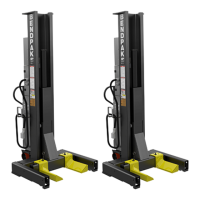
Lubrication
• Raise the lift and Park on the top most safety
position.
• Through the top and bottom of each Column, apply
a light coat of grease on the frontal face and internal
face of the Column Rails. See Figures A & B below.
Column Rails
Brass Sliders
Fig. A
Fig. B
Bleeding
1. After electrical power is connected and oil reservoirs
are full, press “UP” button to raise lift.
2. Continue raising until the fork arms are positioned
approximately 36” above oor level.
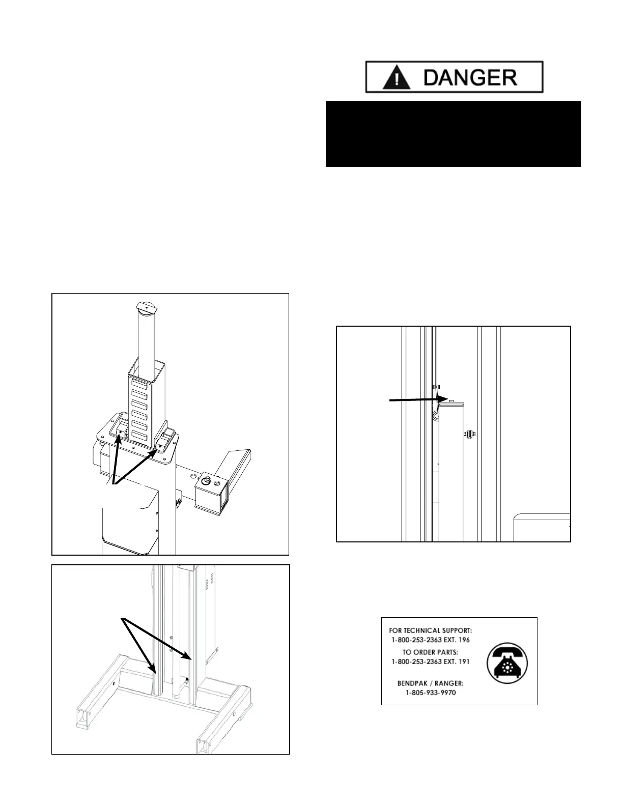
3. Slowly loosen the BLEED SCREWS, one by one,
located at the top of each cylinder to bleed trapped air.
DO NOT completely remove bleed screws. Re-tighten
after trapped air has escaped. (See Figure below).
4. Lower the lift completely. Wait ve minutes and
repeat bleeding process one additional time.
THE LIFT WILL MOVE DOWN WHEN BLEEDING.
MAKE SURE ALL EQUIPMENT, PERSONNEL,
HANDS AND FEET ARE CLEAR BEFORE
PERFORMING THE CYLINDERS BLEEDING.
Cylinder
Bleed
Screw
DO NOT
completely
remove
Bleed Screw.
One full turn
should purge
trapped air.