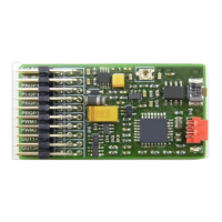
2. Connection
Plugs (from top to bottom)
1. External amplifier (optional)
2. Speaker
3. Prop1 Input (Speed IN)
4. Prop1 Output (Speed OUT)
5. Prop2 Input (optional)
6. Prop3 Input (optional)
7. PWM1 (Servo 1 or Out 10)
8. PWM2 (Servo 2 or Out 11)
9. Out 1+2 switching output
10. Out 3+4 switching output
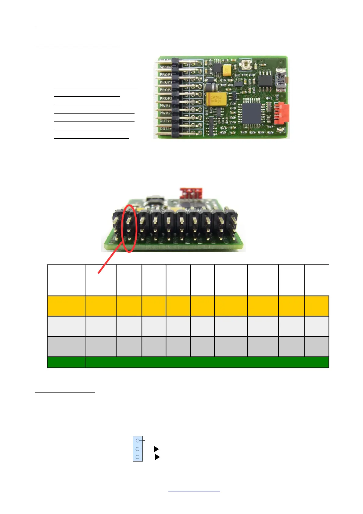
Watch plug orientation
!!! Signal lead is always on TOP (orange or white) !!!
Ext.
Amplifier
Speaker
PROP
1 In
PROP
1 Out
PROP
2 In
PROP
3 In
PWM 1
(OUT 10)
PWM 2
(OUT 11)
OUT
1+2
OUT
3+4
NC
Speaker
Plus
Signal
(In)
Signal
(Out)
Signal
(In)
Signal
(In)
Signal
(Out)
Signal
(Out)
OUT 2
(Minus)
OUT 4
(Minus)
Signal
Speaker.
Minus
Plus Plus Plus Plus Plus Plus Plus Plus
Minus Frei Minus Minus Minus Minus Minus Minus
Out 1
(Minus)
OUT3
(Minus)
External amplifier:
Most commercial amplifier modules with high impedance input can be connected directly.
Volume is set on the TBS Mini. If a common servo cable is used for making the audio connection,
RED is signal and BROWN is ground. DO NOT CONNECT A SPEAKER TO THIS PORT !!!
TBS Mini V2, 11/2018 www.benedini.de Page 4 of 13
Prog. Cable