-10- -11-
Tested
ground end to
Auxiliary ground nail
TEST
HOLD
HV
PRES S
TO TEST
CAT.III 60 0V
LOCK
OFFOFF
2000Ω
(2WI RES)
2000Ω
200Ω
20Ω
EART H
E
P
(
S
)
ACV
C
(
H
)
MAX
AC200 V
VOLTAG E
red
yellow
green
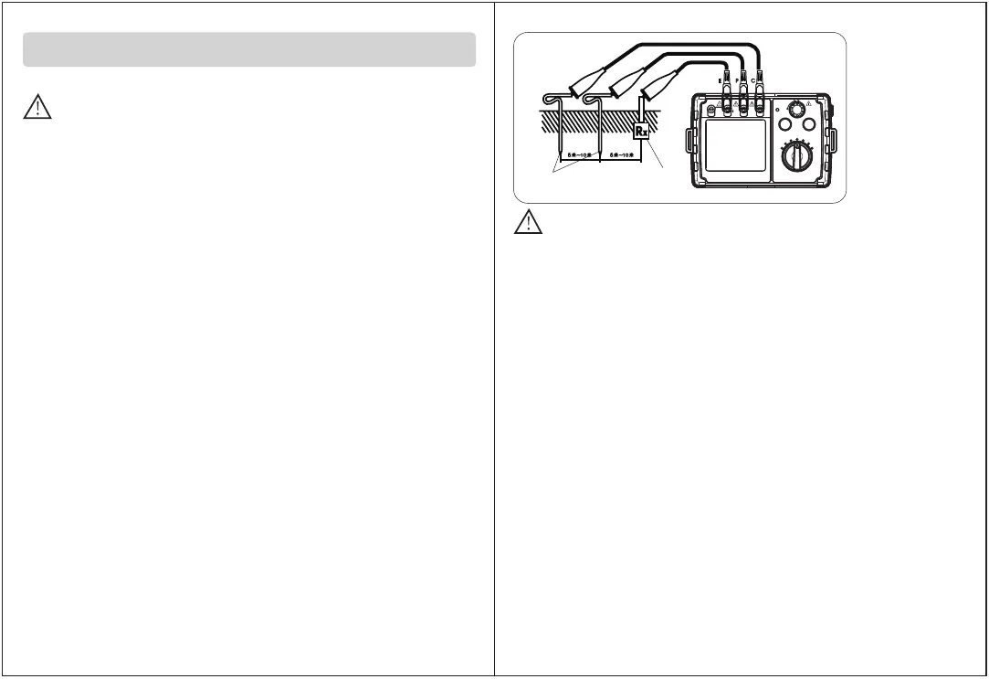
C:Auxiliary electrode
P: Point electrode
E:tested electrical end
Figure3
caveat
Ground voltage test is only performed on the V and E ends, and the
connection between C and P ends must be disconnected, otherwise
it may cause danger or damage to the instrument.
c. Ground resistance test: Rotate function selection switch to 2000Ω
(maximum gear), and press "TEST" button, with LCD displaying
ground resistance value. If the measured resistance value is less
than 200Ω, turn function selection switch to the connection.
20Ω gear of ground resistance is, and LCD displays ground resistance
value. You can also measure in the order of other gears. Be sure to select
suitable gear to measure to make sure the measured value the most accurate.
When you press "TEST" button, status indicator on the button will light up,
indicating that the instrument is under test state.
(Note: if test lead of C or E end have poor contact, auxiliary ground
resistance or ground resistance is too large (such as more than 32KΩ
for 20Ω gear), or the test terminal is open, LCD will display "---- Ω".
At this time, please check whether line connection is good, the soil is
too dry, and the auxiliary grounding nail is reliably grounded.)
When the measured ground resistance is greater than measurement
range of this gear, that is, In case that the 20Ωlevel is between 20.5Ωand
32KΩor the 200Ωlevel is between 205.0Ωand 43KΩor the2000Ωis between
2050Ωand 65KΩ., the LCD will display “OL” (over range).
Measurement method
When the instrument performs ground resistance function test,
a maximum voltage of about 50V~ will be generated between E-C
end s. Do not touch the exposed metal part of test lead and auxiliary
ground nail to avoid electric shock.
caveat
3.1 Accurate measurement (tested with standard test lead):
a. pound P and C ground nails deeply into the ground, line them and
equipment to be measured in a line (straight line) with distance 5
to 10 meters. The connection method is shown in Figure 3:
(Note: Make sure ground nail is pressed in wet soil. If the soil is dry,
add enough water; stone or sand must also be wet before testing.
If it is difficult to make auxiliary ground piles in concrete areas of
urban areas, you can lay two steel plates of 25cm*25cm (or use
existing auxiliary ground nails) flat on the concrete floor and apply
wet towel, pour enough water to replace measuring electrode.
Generally, the measurement can be performed.)
b. Ground voltage test: The function selection switch is screwed to the
ground voltage range, and LCD displays ground voltage measurement.
Status: Insert test leads into V and E ends (do not insert test leads into
other test ends) and then connect to the test point, LCD will display
measured value of ground voltage (note: do not press TEST button
when measuring the ground voltage), if measured value is> 10V,
turn off relevant electrical equipment, and perform ground resistance
test after ground voltage declines, otherwise it will affect test accuracy
of ground resistance.
SAVE
 Loading...