Benewake (Beijing) Co. Ltd.
Page13
Start Slave Addr W Ack Register Addr Ack Stop
Start Slave Addr R Ack Data1 Ack … DataN Nack Stop
Note that only in the read register timing: the first Stop signal is fine to be omitted, and an Ack signal
is also working while replacing the last Nack signal.
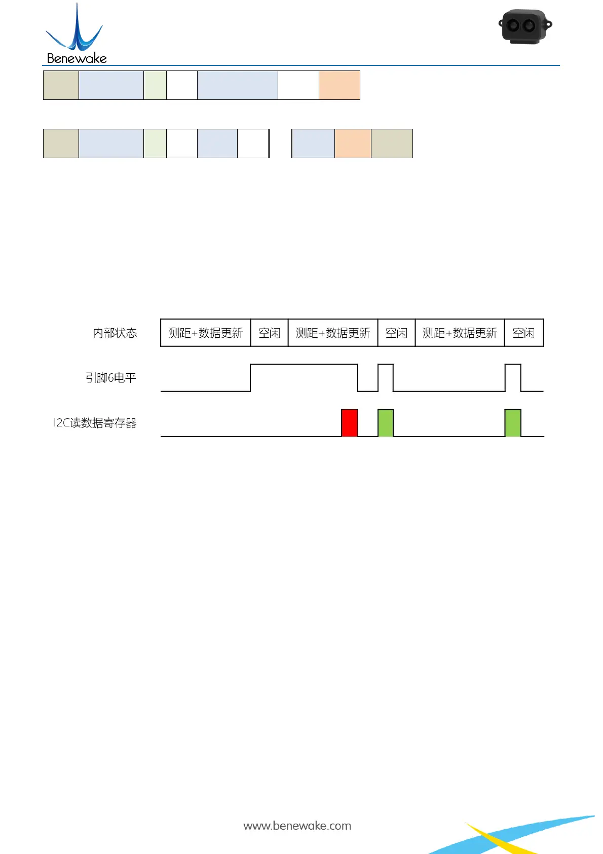
In the continuous ranging mode, the host must monitor pin 6 for synchronous signal and initiate the
read data operation in time. Otherwise, it may cause an error by reading and updating the data register at
the same time. In multi-machine bus mode, use command to trigger reading is strongly recommended.
Figure 5 Timing of reading data register in I2C mode
Pin 6 is normal low level and it switches to high as soon as the data is updated. It switches to low
level only if a read operation on any register is done. Therefore, I2C host must read the register when
receive a high level on pin 6 in the continuous ranging mode. As the figure has shown above, the first
result in red is unreliable and the rest two in green are accurate.
To writing the configuration value to the I2C register does not take effect immediately, nor will the
power outage be saved, but writing 0x01 to address 0x20 will save the current register value and take
effect after restarting. If the written configuration value is invalid, the register value remains valid.
Generally, only writable register addresses take effect immediately after being written.
Normally write registers that are only writable are saved and start working immediately. However,
changing a value of an I2C register is not. The changed value in I2C register are saved and effective after
reboot only if the new value is valid and address 0x20 is written with value 0x01.

 Loading...