BRAIN 24 control unit
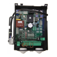
The BRAIN 24 electronic control unit may be used for the control of 1 or 2 motors 24Vdc with power not higher than 80W+80W.
GENERAL WARNINGS
a) The electrical installation and the operating logic must comply with the regulations in force.
b) The leads fed with different voltages must be physically separate, or they must be suitably insulated with additional insulation of
at least 1 mm.
c) The leads must be secured with an additional fixture near the terminals.
d) Check all the connections again before switching on the power.
e) The unused N.C. inputs must be bridged.
INPUT/OUTPUT FUNCTIONS
BRAIN 24 Control unit
Terminal No.FunctionDescription
1-2Motor 1Connection, motor 1: 24VDC 80W max
3-4Motor 2Connection, motor 2: 24VDC 80W max
5-6Flashing lightConnection, flashing light 24VDC 15W max.
7-8LockOutput, 12VAC/10W (5s) power supply for electric lock (7:0V, 8:+12V)
9-10SCA/2°Ch radio
Normally open clean contact. Controlled by “2Ch” logic.
With 2ch logic Off: SCA contact, open gate indicator.
With 2ch logic On: Contact controlled by 2
nd
radio channel of the receiver.
Note: with “SRL” logic On, it performs the contact function of the courtesy light control, see
table of logic.
11-1224 Vac/dc
Output, accessory power supply, 24VAC/0.5A max.
IMPORTANT: If the battery charger board CB.24V is installed, the output (without mains power
connected) has a 24Vdc polarised voltage.
Make sure the devices are correctly connected (i.e. 11:+24Vdc / 12:-24Vdc).
13COMCommon for limit switches and all control inputs.
14SWO1Input, OPEN limit switch, motor 1 (Normally closed contact)
15SWC1Input, CLOSE limit switch, motor 1 (Normally closed contact)
16SWO2Input, OPEN limit switch, motor 2 (Normally closed contact)
17SWC2Input, CLOSE limit switch, motor 2 (Normally closed contact)
18PHOTInput, photocell activated in both opening and closing phases
19PHOT CInput, photocell activated in closing phase only
20STOPInput, STOP push-button (Normally closed contact)
21OPENInput, OPEN push-button (Normally open contact).
22CLOSEInput, CLOSE push-button (Normally open contact)
23PED
Input, push-button for pedestrian use (Normally open contact), it controls the complete
opening of motor 1
24Step-by-StepInput, step-by-step push button (Normally open contact)
25COMCommon for all control inputs.
26-27BAR
Input, sensitive edge contact
Resistive edge: “DAS” Jumper closed
Mechanical edge: “DAS” Jumper open
When the edge is activated, the gate movement is stopped and reversed for about 3s.
30-31AntennaConnection to the insertable radio receiver card (30-signal/31-screen).
JF1-JF224VAC/dc
Input, 24VAC/24VDC power supply.
If buffer batteries are used, connect the CB.24V card (in option) as indicated in the table.
Programming
The programming of the various functions of the control unit is carried out using the LCD display on the control unit and setting
the desired values in the programming menus described below.
The parameters menu allows you to assign a numerical value to a function, in the same way as a regulating trimmer.