24
8) CP.B6-1024 TURBO CONTROL UNIT
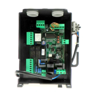
8.1) WIRE DIAGRAM
Wire connections shown in Fig. 17 are described hereunder:
M2 SEL. 115V
Mains power supply se-
lection
230Vac 50/60Hz (from 207Vac to 253Vac) M2 OPEN jumper
115Vac 50/60Hz (from 102Vac to 125 Vac) M2 CLOSED jumper
L-N-GND Mains power supply Mains power supply input selectable via M2 jumper.
+ BATT - Batteries Input for connecting buffer batteries (accessory) 2x12V 2.1Ah
M11 Motor 24Vdc motor connection
+ 24 - 24 Vdc Accessories power supply output 24Vdc 0.8 A max (respect accessories polarity).
AUX1 AUX 1 Auxiliary output Output with N.O. contact configurable by AUX1 operating logic
BAR J3 Responsive sensor
Responsive sensor contact input
Resistive sensor: Jumper "DAS" closed
Mechanical sensor: Jumper "DAS" open
The sensor stops the movement of the door and reverses it for about 3s.
If the sensor is not used: Jumper "DAS" open, jumper between BAR terminals.
RELEASE SW. Magnetic Sensor
Input for safety microswitch connected to the release lever. Motor stops IF RELEASE LEVER OPEN.
All LED segments are on.
S.I.S.
Synchronisation card
optional
Optional SIS card input for synchronising two opposing automations.
See paragraph synchronisation of two automations.
BLINK Flashing 24Vdc output 15W max. for connection to the flashing light.
AUX2 Auxiliary output AUX 2 24 Vdc output configurable by AUX2 operating logic (0.5A max)
COM Common Inputs Common for all control inputs.
SWO Limit switch opens Limit switch input OPENS (N.C. contact).
SWC Limit switch closes Limit switch input CLOSES (N.C. contact).
STOP STOP Button input STOP (N.C. contact).
PHO
Photocell opening/closing
Photocell input active in opening and closing (N.C. contact).
PHC Photocell closing Photocell input active only during closing (N.C. contact)
OPEN Opens Input for configurable opening command as pedestrian input (N.O. contact)
CLOSE Closes Close command input (N.O. contact)
PP Step-by-step Step-by-Step button input (N.O. contact)
COM Common Inputs Common for all control inputs.
ANT-SHIELD Antenna
Built-in radio transmitter card antenna connection (ANT-signal/SHIELD-screen).
8.2) PROGRAMMING
The programming of the various functions of the control unit is carried out using the LCD display on the control unit and setting the desired values in
the programming menus described below.
The parameters menu allows you to assign a numerical value to a function, in the same way as a regulating trimmer.
The logic menu allows you to activate or deactivate a function, in the same way as setting a dip-switch.
8.2.1) TO ACCESS MANUAL PROGRAMMING
1 -Press the <PG> button to enter the first Installation menu “INST”.
2 -Choose with <+> or <-> button the menu you want to select (see menu at page 10-11)
3 - Press the button <PG>, the display shows the first function available on the menu.
4 - With the <+> or <-> button, select the function you want.
5 - Press the button <PG>, the display shows the value currently set for the function selected.
6 - With the <+> or <-> button, select the value you intend to assign to the function.
7 - Press the button <PG>, the display shows the signal “PRG” which indicates that programming has been completed.
8.2.2) PROGRAMMING NOTES
Simultaneously pressing <+> and <-> from inside a function menu allows you to return to the previous menu without making any changes. Hold down
the <+> key or the <-> key to accelerate the increase/decrease of the values.
Hold down the <+> key or the <-> key to accelerate the increase/decrease of the values.
After waiting 120s the control unit quits programming mode and switches off the display.
When the board is switched on, the software version is displayed for around 5 sec
The pre-set logic functions and parameters are made taking account of a typical installation.
8.3) TESTING
- Check that the safety devices work correctly.
- Check the opening/closing forces at the points set out in EN 12445 with an appropriate instrument.
- If the forces are greater, install a safety device compliant with EN12978 (e.g. safety sensitive edge) and repeat the measurements.
- Check the correct setup of the operation logic and that the manual release works properly.

 Loading...