14
1
2
3
4
5
PHOT
STOP
PP
RXTX
24V
-
+
BLINK
SHHIELD
ANT
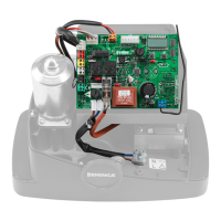
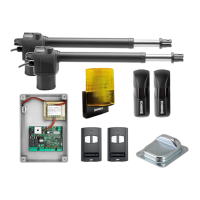
Control unit CP.PONY connections
Except for the mains connection cable, all electric connections
have a voltage of 24V and can also be performed by unquali-
fied staff.
Connect all accessories making reference to the layout in figure
33 and to the “Electric connections” paragraph, for that con-
cerning the types of cable.
To make connection easier, the accessory clamps have colours
that correspond to those of the control unit.
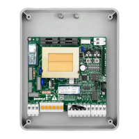
Fig.1
KEY:
1 Line protection fuse
2 Accessories protection fuse
3 “PGM” programming button
4 Programming button “5”
5 LCD
A B
DESCRIPTION OF THE TERMINAL BOARDS
CLAMP COLOUR DESCRIPTION
PHOT GREEN
NC input from the RX photocell. The two clamps are connected to each other by a wire (ref. “A”).
Remove this wire only if the photocell is connected.
STOP BLACK
STOP input NC contact for auxiliary “STOP” command (optional). The two clamps are connected to
each other by a wire (ref. “A”). Remove this wire only if a device is connected to this input.
PP WHITE
Step-by Step’ command input from the key selector. At every impulse sent from the selector a
sequence of commands, which can be configured using the PP function, is performed cyclically.
24V YELLOW 24Vdc output for photocells power supply. Respect the polarities + and - in the connections (ref “B”).
BLINK RED 24Vdc flashing light connection output
SHIELD/ANT BLUE
Connection of the aerial built-in the flashing light.
When connecting the RG58 cable, the external shield must be connected to the SHIELD clamp.
 Loading...