18
TRUST24 CONTROL PANEL
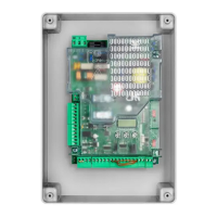
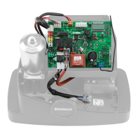
ELECTRICAL CONNECTIONS
The following table shows the electrical connections in Fig. 1:
Terminals Function Description
L-N-GND Supply Mains input 115-230Vac 50-60Hz
+ BATT - Batteries Input for connection of the back-up batteries (accessory)
M0T1 Motor 1 Connector for connection of 24 Vdc MOT1
M0T2 Motor 2 Connector for connection of 24 Vdc MOT2
BLINK Flashing light 24Vdc flashing connection 4W max.
LOCK Electric lock Electric lock connection.
AUX1 AUX 1 auxiliary output
Output with configurable N.O. contact from working parameter AUX1. Max load 500
mA.
+ 24V - Output 24Vdc
Power supply output accessories 24Vdc/0.5A max.
ATTENTION!! With ESA:ON logic, during the Stand-by phase, the power supply of
the accessories is interrupted. See ESA Logic
BAR Sensitive edge
Sensitive bar contact input, a resistor is pre-installed on the terminals of 8,2 KOhm.
Resistive bar 8K2: connect the bar to the terminals eliminating the pre-installed resis-
tance as indicated in Figure 1.
Mechanical bar: connect the bar in series to the resistance as indicated in Figure 1.
The intervention of the bar stops movement of the gate and inverts for approx. 3s.
+AL.ENC.- Encoder power supply
Encoder power supply
Power supply output for Encoder M1 and M2. Use a 3x0,5mm
2
cable max. length 10m..
COM Limit switch common Common for limit switch inputs SW01/SW02/SWC1/SWC2
SW0/E1 FC/Encoder input 1 Input for limit switch contact Open Motor 1 or for signal Encoder Motor 1
SWC1 FC input Input for limit switch contact Motor 1 closing
SW0/E2 FC/Encoder 2 input Input for contact limit switch Open Motor 2 or for signal Encoder Motor 2
SWC2 FC input Input for limit switch contact Motor 2 closing
PHOT OP Photocell OPEN Photocell input enabled in OPENING and CLOSURE (N.C. contact).
PHOT CL Photocell CLOSE Photocell input enabled in CLOSURE (N.C. contact).
STOP STOP STOP button input (N.C. contact)
OPEN OPENED OPEN button input (N.O. contact). You can connect a timer for opening in time slots.
CLOSE CLOSED CLOSE button input (N.O. contact).
PED PEDESTRIAN
Pedestrian button input (N.O. contact), opening command of motor 1, see TPED pa-
rameter.
P.P. Step-by-Step
Step-by-Step button input (N.O. contact). You can connect a timer for opening in time
slots.
COM Common Inputs Common for the inputs for control and photocells and STOP
AUX2 AUX 2 auxiliary output
Output with configurable N.O. contact from working parameter AUX1. Max load 500
mA.
ANT-SHIELD Antenna
Integrated radio-receiver board antenna connection
(FRONT: Signal - SHIELD: Screen)
EXP1 Extension 1 Expansion connector for serial KNX or pro.UP
EXP2 Extension 2 Expansion connector for serial pro.UP
 Loading...