Do you have a question about the Bennett Marine BOLT129 and is the answer not in the manual?
Boosts visibility by keeping the bow down at lower speeds for safer operation in various conditions.
Improves fuel economy by reducing engine labor and enabling quicker planing.
Enhances boat performance by lifting the stern proportionally to speed and load changes.
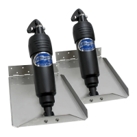
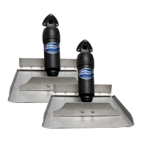
Details specifications for trim tab sizes, materials, and mounting options.
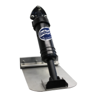
Lists specifications for available actuator models, including hinge types and materials.
Specifies types of relay modules available, featuring diagnostics and auto retraction.
Outlines requirements for helm controls, mentioning circuit breakers or fuses.
Notes its use for dual station or dual actuator applications.
Explains how trim tabs are mounted and operated, and their effect on the boat's attitude.
Describes the reverse relationship between tab movement and bow direction for intuitive control.
Guides on how to achieve and maintain the desired planing attitude for efficient boat operation.
Explains a test to find the boat's best running attitude for optimal performance.
Provides advice on gradually using trim tabs and avoiding over-trimming.
Details how to use trim tabs individually to correct boat list or tilt.
Explains how to coordinate trim tabs with engine trim for enhanced speed and power.
Advises to use 'Bow Down' on both tabs to improve handling in choppy seas.
Recommends fully retracting tabs in following seas for control and to prevent bow digging.
Provides guidance on adjusting tabs to manage windward sides in choppy conditions.
Instructions for lowering tabs to lift the stern and lower the bow for improved hole shots.
Describes how to address porpoising by using 'Bow Down' in short bursts.
Highlights important safety advice, including avoiding over-trimming and using caution.
Initial steps for actuator and tab installation, including safety checks and mounting location considerations.
Illustrates the standard mounting procedure for trim tabs on V-hull boats.
Lists the necessary tools and materials required for actuator and tab installation.
Guidance on tab placement relative to the chine and drive unit, using backing plates.
Steps for attaching actuators to trim tabs, including hinge assembly and final positioning.
Procedures for mounting fixed and adjustable upper hinge actuators to the boat transom.
Instructions for connecting actuator wires to the harness connector and ensuring proper pin alignment.
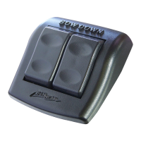
Description of the basic rocker switch control and its plug-and-play installation.
Overview of the waterproof control with diagnostics and Auto Tab Retraction features.
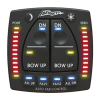
Details the control with diagnostics, indication LEDs, and Auto Tab Retraction features.
Steps for preparing the console, marking, and drilling holes for the rocker switch control.
Instructions for seating the control plate and securing it with screws.
How to connect port and starboard extension cables to the rocker control.
Wiring the orange power wire and black ground wire for the rocker switch.
Steps for preparing the console, marking, and drilling holes for the BCN control.
Instructions for placing and securing the BCN helm display keypad.
Wiring the orange wire for power and purple wire for auto tab retraction.
Notes that a relay module is required for the BCN control system.
Steps for preparing the console, marking, and drilling holes for the BCI control.
Instructions for placing and securing the BCI helm display keypad.
Wiring the orange wire for power and purple wire for auto tab retraction.
Notes that a relay module is required for the BCI control system.
Clarifies that relay module installation is not required for BRC installations.
Guidance on selecting a dry location and mounting the relay module.
Instructions for connecting the ground wire and power supply to the relay module.
Steps for connecting the 3 ft. extension cable from the display to the relay module.
Details on actuator/display extension cables and proper routing through the boat.
Instructions for connecting extension cables and reconnecting the battery to check functionality.
Steps to power up the system, including battery, gauge, and ignition switches.
Tests to verify port and starboard actuator extension and retraction via control buttons.
Directs users to the troubleshooting section for issues not covered.
Wiring diagrams for BCI/BCN and BRC controls with single actuators.
Wiring diagram for systems with one display controlling two actuators.
Wiring diagram for systems with two displays controlling one actuator.
Wiring diagram for systems with two displays controlling one actuator.
Wiring diagram for systems with two displays controlling two actuators.
Templates for accurately cutting holes for the BRC rocker switch control.
Templates for accurately cutting holes for the BCI or BCN control units.
Templates for marking mounting hole locations for BEA2000 fixed upper hinge actuators.
Templates for marking mounting hole locations for BEA3000 adjustable upper hinge actuators.
Routine checks for electrical connections and advice on cold weather operation.
Recommendations for zinc anodes to deter electrolysis in saltwater environments.
Guidance on cleaning and painting tabs to discourage marine growth.
Important safety advice regarding malfunctions, wiring, stepping on tabs, and extended actuators.
Checks for power, fuses, ground connections, and voltage for BRC systems.
Steps to inspect and reseat actuator connector contacts for proper connection.
Troubleshooting reversed actuator wiring in the connector for BRC systems.
Checks for power, LED status, fuse, voltage, and communications for BCN systems.
Troubleshooting reversed actuator wiring in the connector for BCN systems.
Checks for battery, LED status, and communications for BCI systems.
Steps to inspect and reseat actuator connector contacts for proper connection.
Troubleshooting reversed actuator wiring in the connector for BCI systems.
Diagnosing communication problems between display and relay module for BCI systems.
Troubleshooting for flashing LEDs indicating undetected actuators.
Details the conditions and duration of the limited warranty for Bennett products.
States limitations and exclusions from the express warranty coverage.
Outlines the steps for submitting a warranty claim and part evaluation.
Covers warranty transferability and limitations on remedies and damages.
Bennett's right to modify products without prior obligation for sold items.
Table specifying warranty periods for actuators, control switches, and indicator controls.
Procedure for customers outside the US to handle warranty and returns.
| Brand | Bennett Marine |
|---|---|
| Model | BOLT129 |
| Category | Marine Equipment |
| Language | English |