10/ 2004
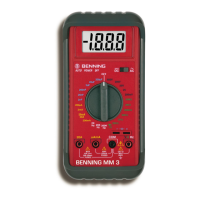
BENNING MM 3
15
direct (DC) or alternating (AC) voltage to be measured.
- Connect the black safety test lead to the COM-terminal
of the
BENNING MM 3.
- Connect the red safety test lead to the input terminal for V, Ω, and Hz
of
the BENNING MM 3.
- Connect the safety test leads to the circuit measurement points and read
the measured value on the digital display of the BENNING MM 3.
see Figure 2: Direct voltage measurement
see Figure 3: Alternating voltage measurement
8.2.2 Current measurement
- Select the appropriate range with the rotary switch
of the
BENNING MM 3.
- Use the selector switch
of the BENNING MM 3 to select the required
direct (DC) or alternating (AC) voltage / current to be measured.
- Connect the black safety test lead to the COM-terminal
of the
BENNING MM 3.
- Connect the red safety test lead to the input terminal for the µA/ mA range
for currents up to 200 mA, or to the input terminal for the 20 A range
for currents between 200 mA and 20 A of the BENNING MM 3.
- Connect the safety test leads to the circuit measurement points and read
the measured value on the digital display of the BENNING MM 3.
see Figure 4: DC current measurement
see Figure 5: AC current measurement
8.3 Resistance Measurement
- Select the appropriate range with the rotary switch
of the
BENNING MM 3.
- Connect the black safety test lead to the COM-terminal
of the
BENNING MM 3.
- Connect the red safety test lead to the input terminal for V, Ω, and Hz
of
the BENNING MM 3.
- Connect the safety test leads to the circuit measurement points and read
the measured value on the digital display of the BENNING MM 3.
see Figure 6: Resistance measurement
8.4 Diode Testing
- Turn the rotary switch
of the BENNING MM 3 to select the appropriate
range identified by a buzzer and diode symbol.
- Connect the black safety test lead to the COM-terminal of the
BENNING MM 3.
- Connect the red safety test lead to the input terminal for V, Ω, and Hz
of
the BENNING MM 3.
- Connect the safety test leads across the diodes and read the measured
value on the digital display of the BENNING MM 3.
- For a typical silicone diode tested in the forward-biased direction a voltage
flow between 0,500 V and 0,900 V is displayed. A display showing "000"
indicates a short circuit in the diode, whereas a display showing "1"
indicates an open circuit in the diode.
- For a diode tested in the reverse-biased direction the display reads "1". If
the diode is damaged, the display will show "000" or other values.
see Figure 7: Diode Testing
8.5 Continuity Testing with Buzzer
- Turn the rotary switch
of the BENNING MM 3 to select the appropriate
range identified by a buzzer and diode symbol.
- Connect the black safety test lead to the COM-terminal
of the
BENNING MM 3.
- Connect the red safety test lead to the input terminal for V, Ω, and Hz
of
the BENNING MM 3.
- Connect the safety test leads to the circuit to be measured. If the circuit
resistance between the COM-terminal and the input terminal for V, Ω and
Hz falls below 50 Ω, then the built-in buzzer in the BENNING MM 3 emits
a continuous tone.
see Figure 8: Continuity Testing with buzzer
8.6 Capacitance Measurement