11/ 2008
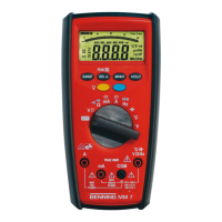
BENNING MM 7
17
Electrical hazard!
Maximum switching-circuit voltage for current measurement,
500 V! If the fuse triggers over 500 V, the unit may be damaged.
A damaged unit may represent an electrical hazard!
8.2.1 Voltage measurement
- With the rotating switch , select the desired function (V) on the
BENNING MM 7.
- With the blue button on the BENNING MM 7, select the type of voltage
to be measured (DC or AC voltage)
- Connect the black safety test lead to the COM socket on the
BENNING MM 7.
- Connect the red safety test lead to the socket for V, Ω, Hz, ºC, ºF, on
the BENNING MM 7.
- Connect the safety test leads to the measuring points. Read the measurement
value displayed in the digital display of the BENNING MM 7.
See fig. 2: DC-voltage measurement
See fig. 3: AC-voltage measurement
8.2.2 Current measurement
- With the rotating switch , select the desired range and function (mA or A)
on the BENNING MM 7.
- With the blue button on the BENNING MM 7, select the type of current
to be measured (DC or AC current).
-
Connect the black safety test lead to the COM socket on the
BENNING MM 7.
- Connect the red safety test lead to the socket for mA range, for current
up to 400 mA or to the socket for the 10 A range, for currents greater than
400 mA up to 10 A on the BENNING MM 7.
- Connect the safety test leads to the measuring points. Read the measurement
value displayed in the digital display of the BENNING MM 7.
See fig. 4: DC-current measurement
See fig. 5: AC-current measurement
8.3 Resistance measurement
- With the rotating switch , select the desired function (Ω) on the
BENNING MM 7.
- Connect the black safety test lead to the COM socket on the
BENNING MM 7.
- Connect the red safety test lead to the socket for V, Ω, Hz, °C, °F, on
the BENNING MM 7.
- Connect the safety test leads to the measuring points. Read the measurement
value displayed in the digital display of the BENNING MM 7.
See fig. 6: Resistance measurement
8.4 Diode testing
- With the rotating switch , select the desired function (Ω/ buzzer and diode
symbol) on the BENNING MM 7.
- Using the blue button on the BENNING MM 7, switch to diode testing
(press button twice).
- Connect the black safety test lead to the COM socket on the
BENNING MM 7.
- Connect the red safety test lead to the socket for V, Ω, Hz, °C, °F, on
the BENNING MM 7.
- Contact the diode connections with the safety test leads and read the meas-
urement value displayed in the digital display of the BENNING MM 7.
- For a normal silicone diode located in flow direction, the flow voltage
between 0.500 V and 0.900 V is displayed. If “000” appears in the display,
there may be a short circuit in the diode. If “1” appears in the display, there
may be an interruption in the diode.
- For a diode located in the non-conducting direction “OL” appears. If the
diode is defective, “000” or other figures appear.
See fig. 7: Diode testing
8.5 Continuity testing with buzzer
- With the rotating switch , select the desired function (Ω/ buzzer and diode
symbol) on the BENNING MM 7.
- Using the blue button on the BENNING MM 7, switch to continuity test
(press button once)
- Connect the black safety test lead to the COM socket on the
BENNING MM 7.
- Connect the red safety test lead to the socket for V, Ω, Hz, ºC, ºF, on
 Loading...